AC_FAIL (AC Input Out of Range / Failure)
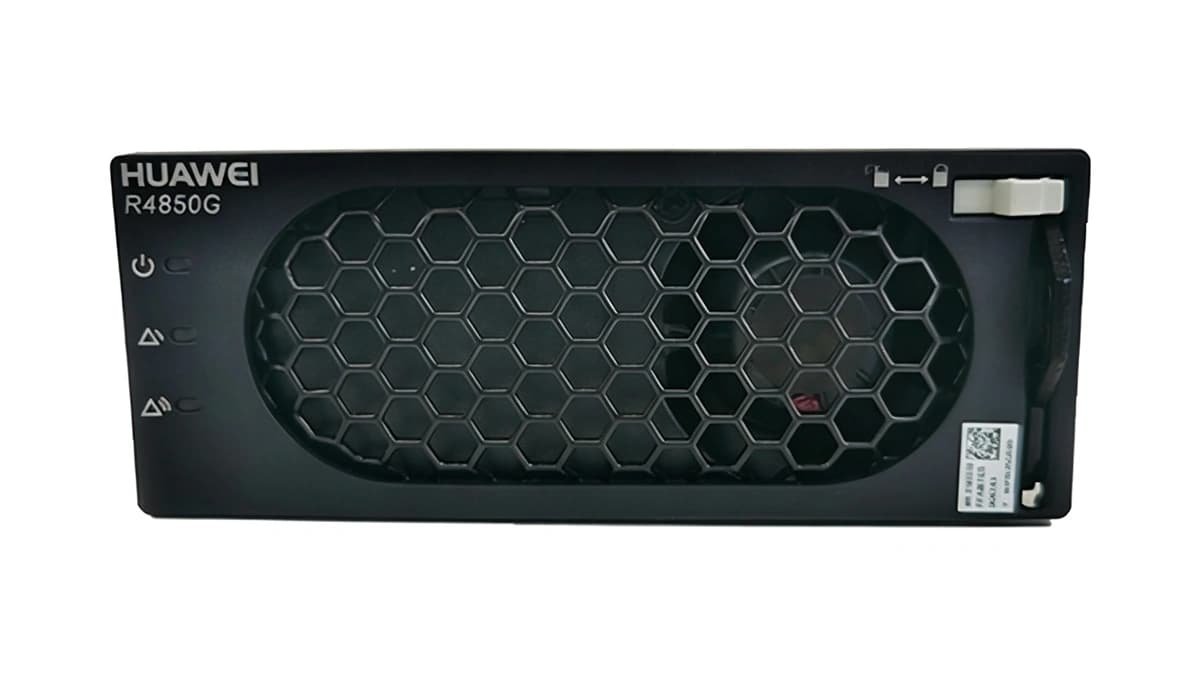
Green LED (Normal) OFF, Yellow LED (Protection) Solid or Blinking
Utility grid outage, phase voltage out of specification (<85VAC or >300VAC), or AC branch breaker open.
1. Verify if the upstream AC miniature circuit breaker (MCB) feeding the rectifier slot has tripped.
2. Measure the AC line-to-neutral (L-N) voltage at the power subrack connector to verify voltage is within 85-300VAC.
3. Reseat the module firmly into the power shelf. If AC voltage is verified correct and alarm persists, replace the rectifier module.
DC_OVP (DC Output Overvoltage Lockout / HVSD)
Green LED (Normal) OFF, Red LED (Alarm) Solid ON
Internal PWM regulation loop malfunction or DC bus transient exceeding hardware shutdown threshold (typically 59.5V ± 0.5VDC), latching the output off.
1. Withdraw the affected rectifier module and disconnect AC input power for at least 30 seconds to discharge capacitors and reset the HVSD latch.
2. Measure the common DC bus voltage to confirm whether another source or CSU controller setting is improperly driving the bus above 58VDC.
3. Re-insert the module. If it immediately re-latches into DC_OVP with a solid Red LED, internal DC/DC secondary control has failed; replace the unit.
OTP_SHUTDOWN (Over-Temperature Protection Shutdown)
Yellow LED (Protection) Solid ON, Green LED OFF or Alternating
Rectifier front air intake blocked, excessive ambient cabinet temperature (>65°C), cooling airflow choked, or internal heatsink thermistor exceeding safe threshold.
1. Inspect and clean the front dust filter and air intake grilles of the ESR-48/56B FC subrack.
2. Check site cooling and cabinet fans; verify that ambient inlet air temperature drops below 45°C.
3. Allow the module heatsink to cool down; the unit will automatically recover once temperature normalizes. If the alarm triggers instantly from a cold start, replace the module due to a defective internal NTC sensor.
FAN_FAIL (Cooling Fan Stalled / Tachometer Fault)
Yellow LED (Protection) Blinking (1Hz), Green LED ON (Derated output)
Mechanical obstruction blocking fan impeller, fan power cable loose, motor bearing seizure, or loss of tachometer pulse feedback to the micro-controller.
1. Visually check the front fan grille for physical debris, wires, or heavy lint blocking the impeller blades.
2. Query the system controller (CSU/Orion) GUI to confirm fan speed alarms and observe whether the fan spins at all or makes grinding noises.
3. If the fan is completely stalled without external obstruction, remove the module and replace the internal fan assembly or the entire rectifier module.
CAN_COMM_LOST (CAN Bus Communication Failure / Unbalance Share)
Yellow LED (Protection) Slow Flash (0.5Hz), Green LED Solid ON (Autonomous mode)
Severed CAN bus link between rectifier and central system controller (CSU), oxidized/bent connector backplane pins, terminating resistor fault, or CAN node ID collision.
1. Partially withdraw the module (~5 cm) and inspect the rear connector for bent signal pins, foreign objects, or burnt pads, then reseat firmly into the slot.
2. Review the CSU controller inventory screen to determine if all modules lost communication; if all failed, verify the shelf CAN cable and 120-ohm bus termination resistor.
3. Swap the failing rectifier to an adjacent known-good slot. If the CAN fault follows the module, the internal CAN transceiver is damaged; replace the module.