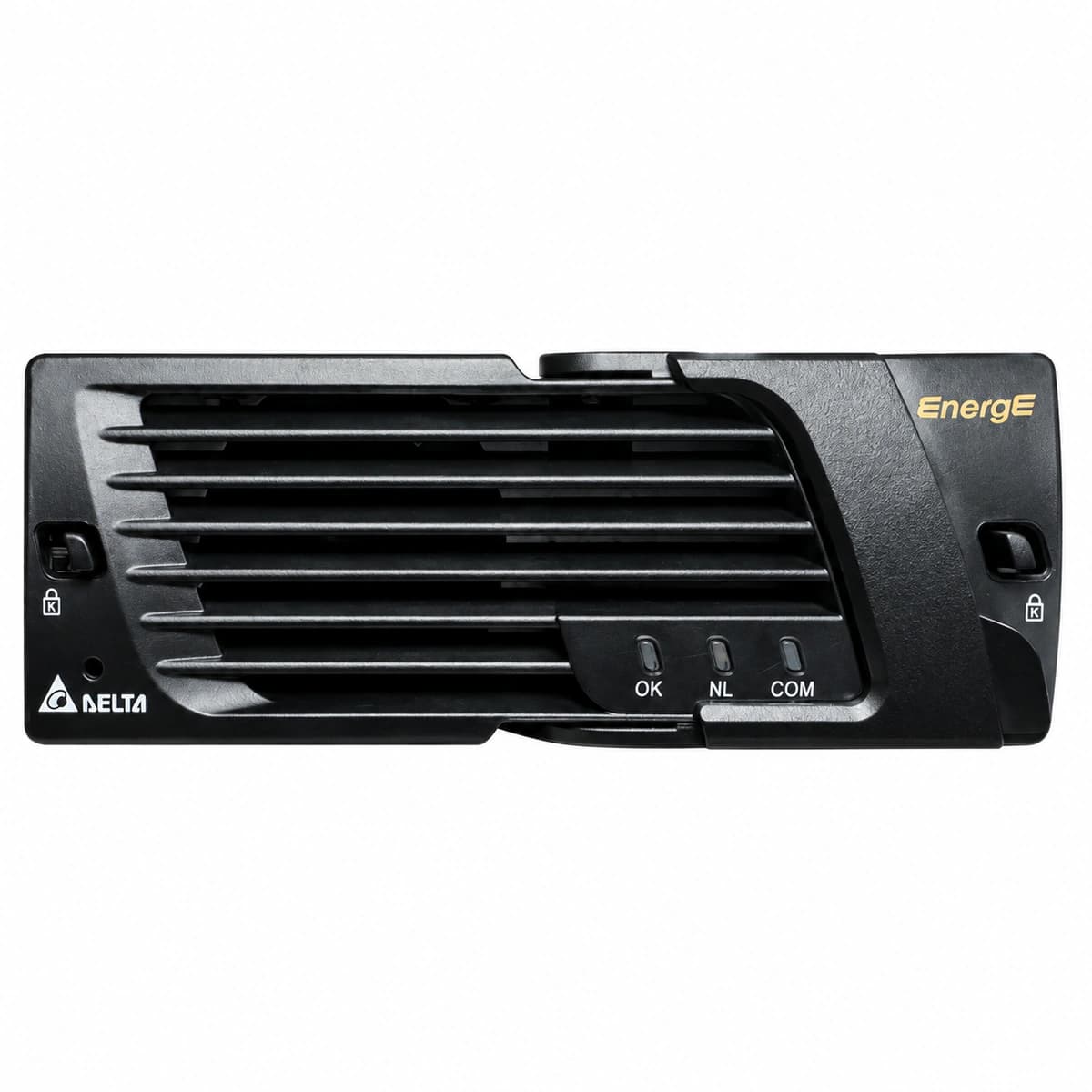
The Delta ESR-48/56CF is an industrial-grade, hot-swappable switch-mode telecommunication rectifier module designed with an advanced high-frequency soft-switching topology and active PFC, engineered to convert a wide AC input range (88V to 300V AC) into a stable, regulated -48V DC output delivering up to 56A (3000W) with outstanding reliability.
Information below comes from the current product catalogue. Confirm the controller, software version and configuration of the installed equipment separately.
Green LED OFF, Red LED solid ON (if powered via bus/aux) or all LEDs OFF
Mains utility outage, AC input voltage <80VAC or >300VAC threshold, upstream circuit breaker trip, or loose AC feed terminal.
1. Measure L-N phase voltage at the rear connector slot using a True-RMS DMM to confirm it is within 85VAC-300VAC.
2. Inspect the rack AC distribution breaker and upstream SPD; reset if tripped only after verifying no short circuit.
3. Reseat the module firmly into the shelf; if AC is verified but alarm persists, replace the module to service internal PFC stages.
Red LED solid ON, Green LED OFF, rectifier output inhibited and latched
Internal DC-DC feedback loop failure, secondary MOSFET/optocoupler puncture, or backfeed from a parallel failed module (>59.5V HW shutdown threshold).
1. Extract the module to physically isolate it; measure DC bus system voltage to verify if system bus or individual unit is faulted.
2. Disconnect AC power to the module for 3 minutes to discharge internal bulk capacitors, then reseat and power up to reset hardware latch.
3. If Red LED latches ON immediately upon restart, internal regulation stage is defective; replace the rectifier immediately.
Amber/Yellow LED solid during power derating; Red LED solid and Green OFF if shutdown threshold reached
Severely clogged front air intake dust filter, ambient shelter temperature >65°C due to HVAC failure, heatsink duct debris, or NTC sensor drift.
1. Inspect shelter HVAC and rack airflow; ensure rectifier intake ambient air temperature is within -40°C to +50°C nominal range.
2. Clean front intake grille, removable dust filters, and rear heatsink fins using dry compressed air.
3. If ambient air and airflow are normal and fan spins at full speed but alarm triggers from cold start, replace the module due to faulty NTC sensor.
FAN_FAIL (Cooling Fan Stall / Tachometer Fault)
Red LED flashing (1Hz) or Amber/Yellow solid ON; controller raises Rectifier Fan Alarm
Mechanical bearing wear/seizure, physical obstruction on blades, loose internal 4-pin fan header, or tachometer (FG) circuit failure.
1. Visually inspect fan blades for physical blockage (zip ties, debris); power off and remove foreign obstructions.
2. Spin blades manually; if significant mechanical resistance or grinding is felt, bearing has seized.
3. Remove module, inspect internal 4-pin fan harness connection; if securely seated but fan does not spin on power-up, replace fan assembly or complete module.
COMM_FAIL (CAN Bus Communication Loss & Current Share Error)
Amber/Yellow LED flashing (0.5Hz), Green LED solid ON; system controller displays 'Module Lost'
Backplane gold-finger edge connector oxidation, open/shorted CAN-H/CAN-L differential lines, or damaged onboard CAN transceiver IC, forcing autonomous default fallback.
1. Check the system controller (e.g., CSU/PSC3) to verify whether all rectifiers are offline (bus topology fault) or only this specific unit.
2. Unseat the rectifier and clean rear gold-finger connectors using isopropyl alcohol; inspect backplane slot for bent or recessed pins.
3. Reseat firmly and lock front latch; if communication does not restore and fault follows the module when swapped to another slot, replace the rectifier.
Access Complete Maintenance & Full Alarm Troubleshooting Manual
This page lists high-frequency critical alarm codes commonly encountered in field maintenance. Comprehensive manufacturer troubleshooting matrices, board-level repair guides, detailed electrical schematics, and firmware commissioning manuals are delivered alongside equipment upon formal project procurement, accompanied by dedicated FAE technical support.
Record the nameplate, system model and controller or module model.
02
Keep the alarm details
Record the full alarm text, indicator colour, timing and whether it persists.
03
Describe recent changes
Note recent replacements, software updates or configuration changes.
Record information visible in the existing interface. Electrical measurements, disassembly and replacement should follow the applicable manufacturer's manual and be performed by qualified personnel.
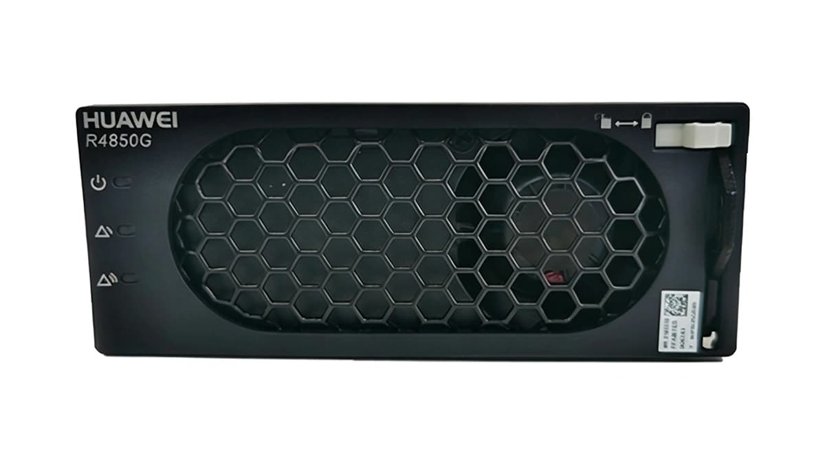
A comprehensive technical breakdown of 48V/50A rectifier modules (Huawei R4850G2 / ETP48400 architecture), covering blind-mate connector pinouts, standalone startup jumpers, CAN 2.0B hex commands for CV/CC adjustment, and active current sharing troubleshooting.