
M500D Equipment information & support
The Emerson (Vertiv) M500D is a carrier-grade microprocessor-based supervisory controller engineered for telecom NetSure -48V DC switch-mode power systems. Featuring live hot-pluggability, high-precision analog-to-digital telemetry acquisition, a backlit graphic LCD, and multi-bus communications, the unit functions as the master intelligence of the power plant, coordinating rectifier groups, battery thermal management, and power environmental alarms.
Equipment information
- Brand
- Emerson
- Equipment model
- M500D
- Equipment type
- System Controllers & Monitoring Units (SMU/CSU)
- Controller / software version
- Confirm against the installed equipment
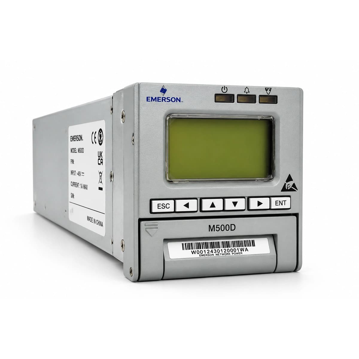
Information below comes from the current product catalogue. Confirm the controller, software version and configuration of the installed equipment separately.
- System Nominal Voltage
- 48V DC
- Communication Interfaces
- RS485, RS232, FE (Ethernet)
- Supported Protocols
- SNMP, Modbus, Emerson Protocol
- Display Interface
- Graphical LCD Screen with Multi-Language Operator UI
- Operating Temperature Range
- -40°C ~ +75°C
- Hot-Swappable Support
- Yes (Live Hot-Pluggable / Plug-and-Play without Power Interruption)
Alarms & troubleshooting
Access Complete Maintenance & Full Alarm Troubleshooting Manual
This page lists high-frequency critical alarm codes commonly encountered in field maintenance. Comprehensive manufacturer troubleshooting matrices, board-level repair guides, detailed electrical schematics, and firmware commissioning manuals are delivered alongside equipment upon formal project procurement, accompanied by dedicated FAE technical support.
Share on-site information
- 01
Identify the exact model
Record the nameplate, system model and controller or module model.
- 02
Keep the alarm details
Record the full alarm text, indicator colour, timing and whether it persists.
- 03
Describe recent changes
Note recent replacements, software updates or configuration changes.
Record information visible in the existing interface. Electrical measurements, disassembly and replacement should follow the applicable manufacturer's manual and be performed by qualified personnel.
Related technical articles
Browse the technical guides or send a question about this model.
View all articlesNeed a replacement module or supporting equipment?
Confirm the full model, system configuration and compatibility requirements before enquiring about suitable products.
Have a model and an on-site issue?
Share the exact model, alarm text and observed symptoms to help identify relevant information and compatibility requirements.