Information below comes from the current product catalogue. Confirm the controller, software version and configuration of the installed equipment separately.
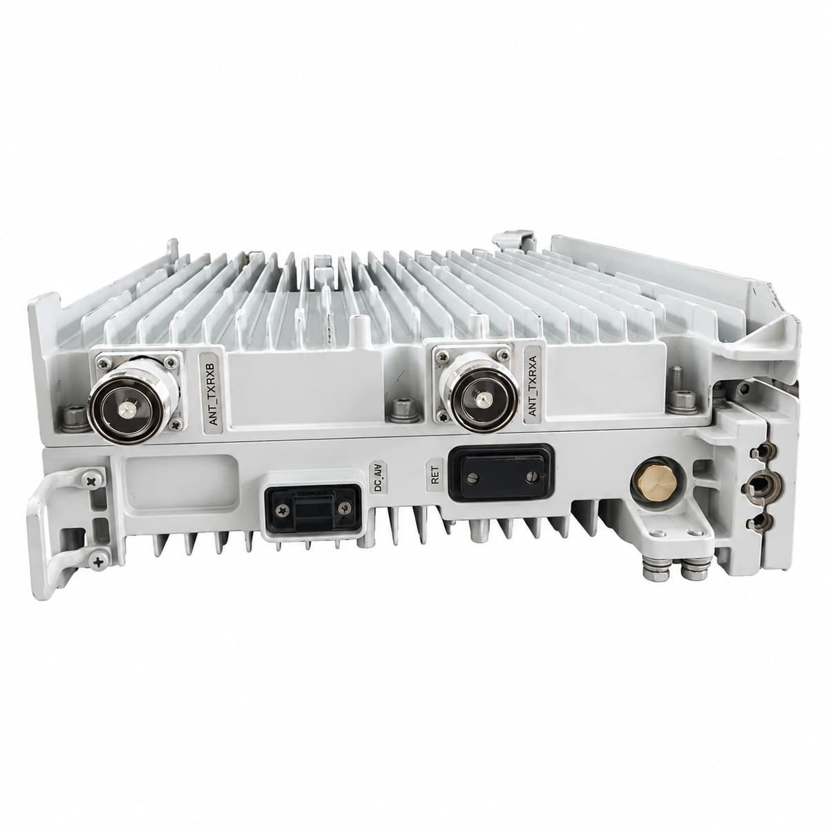
Damaged RF jumper cable, water ingress in feeder connectors, loose RF connector, or antenna impedance mismatch causing excessive reflected power
1. Inspect and torque all RF jumper connections between RRU ports and the antenna system.
2. Perform a VSWR/return loss test on the feeder path using an antenna analyzer (target VSWR < 1.5).
3. Check weatherproofing seals and replace damaged jumpers or water-ingress connectors.
4. If the antenna line is clear but the alarm persists on the branch, replace the RRU3959.
ALM-26521 CPRI Optical Interface Performance Degraded / Loss of Signal
CPRI0 LED steady red, RUN LED blinking slowly, ALM LED steady red
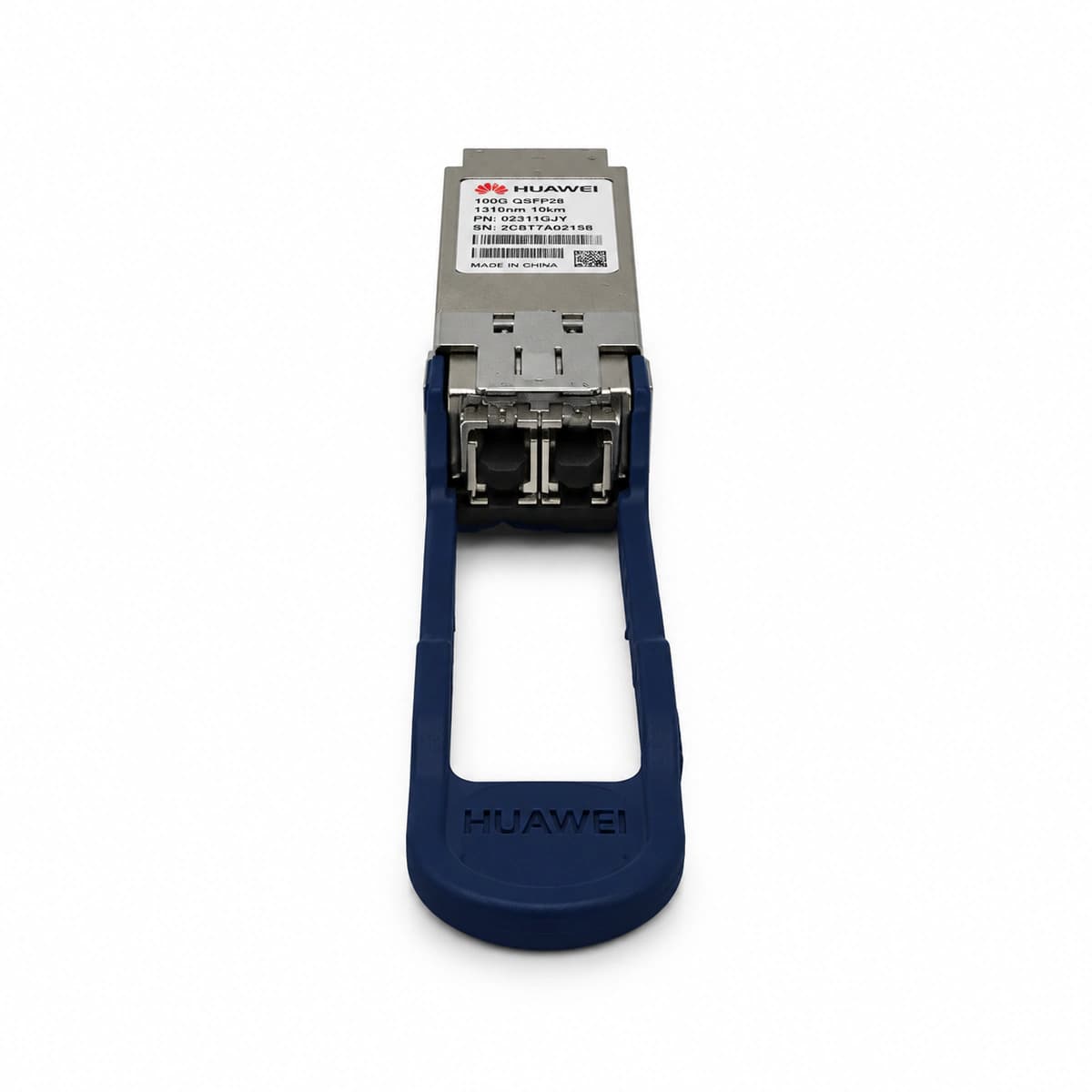
Optical fiber broken or excessively bent between BBU and RRU, failed SFP module, contaminated LC connector end-face, or Rx optical power below threshold
1. Inspect CPRI fiber patch cord and outdoor armored cable for physical damage or sharp bends.
2. Measure Rx optical power at the RRU CPRI port using an optical power meter (normal range: -15 dBm to -9 dBm).
3. Clean LC fiber connectors and SFP transceivers with dedicated optical cleaning tools.
4. Replace SFP transceiver modules at both RRU and BBU sides; replace fiber if attenuation remains out of spec.
ALM-26525 RF Unit DC Power Input Out of Range
RUN LED blinking fast or solid red, ALM LED steady red
Loose DC cable connections, excessive line voltage drop, tripped/faulty DCDU circuit breaker, or DC voltage beyond operating limits (-36V DC to -57V DC)
1. Measure the input DC voltage directly at the RRU power connector using a digital multimeter (normal range: -36V DC to -57V DC).
2. Inspect DCDU circuit breakers, DC distribution box terminals, and ensure screws are torqued without oxidation or thermal discoloration.
3. Verify DC wire gauge against run length; upgrade cable cross-section if line drop causes undervoltage under heavy RF load.
4. If measured DC voltage is stable within specs but alarm persists, replace the RRU3959 unit.
ALM-26524 RF Unit Temperature High Alarm
ALM LED steady red, RUN LED steady green or blinking slowly
Ambient temperature exceeding +55°C limit, passive heatsink fins blocked by debris, missing solar shield, or internal thermal sensor failure causing PA protection derating
1. Clean debris, dust, bird nests, or leaves from between the passive heatsink fins of the RRU.
2. Ensure clearance requirements around the RRU are met (at least 500 mm free space for airflow).
3. Verify that the sunshield is properly installed if the unit is subjected to direct high solar radiation.
4. If airflow and ambient conditions are normal but the alarm persists, replace the RRU3959.
ALM-26531 RF Unit Hardware Fault / Power Amplifier Failure
RUN LED off or steady red, ALM LED steady red, ACT LED off
Internal intermediate frequency (IF) processing IC failure, internal DC-DC power rail fault, PLL unlock, or PA transistor breakdown
1. Issue the MML command `RST RRU` from the BBU LMT/NMS to execute a remote software reset.
2. Power-cycle the RRU by tripping its dedicated DC breaker, wait 3 minutes, and restore power for a cold reboot.
3. Collect RRU alarm logs and check hexadecimal error sub-codes on the OSS to identify the failed internal module.
4. If the hardware self-test fails upon reboot and the alarm immediately recurs, replace the faulty RRU3959.
Access Complete Maintenance & Full Alarm Troubleshooting Manual
This page lists high-frequency critical alarm codes commonly encountered in field maintenance. Comprehensive manufacturer troubleshooting matrices, board-level repair guides, detailed electrical schematics, and firmware commissioning manuals are delivered alongside equipment upon formal project procurement, accompanied by dedicated FAE technical support.
Record the nameplate, system model and controller or module model.
02
Keep the alarm details
Record the full alarm text, indicator colour, timing and whether it persists.
03
Describe recent changes
Note recent replacements, software updates or configuration changes.
Record information visible in the existing interface. Electrical measurements, disassembly and replacement should follow the applicable manufacturer's manual and be performed by qualified personnel.