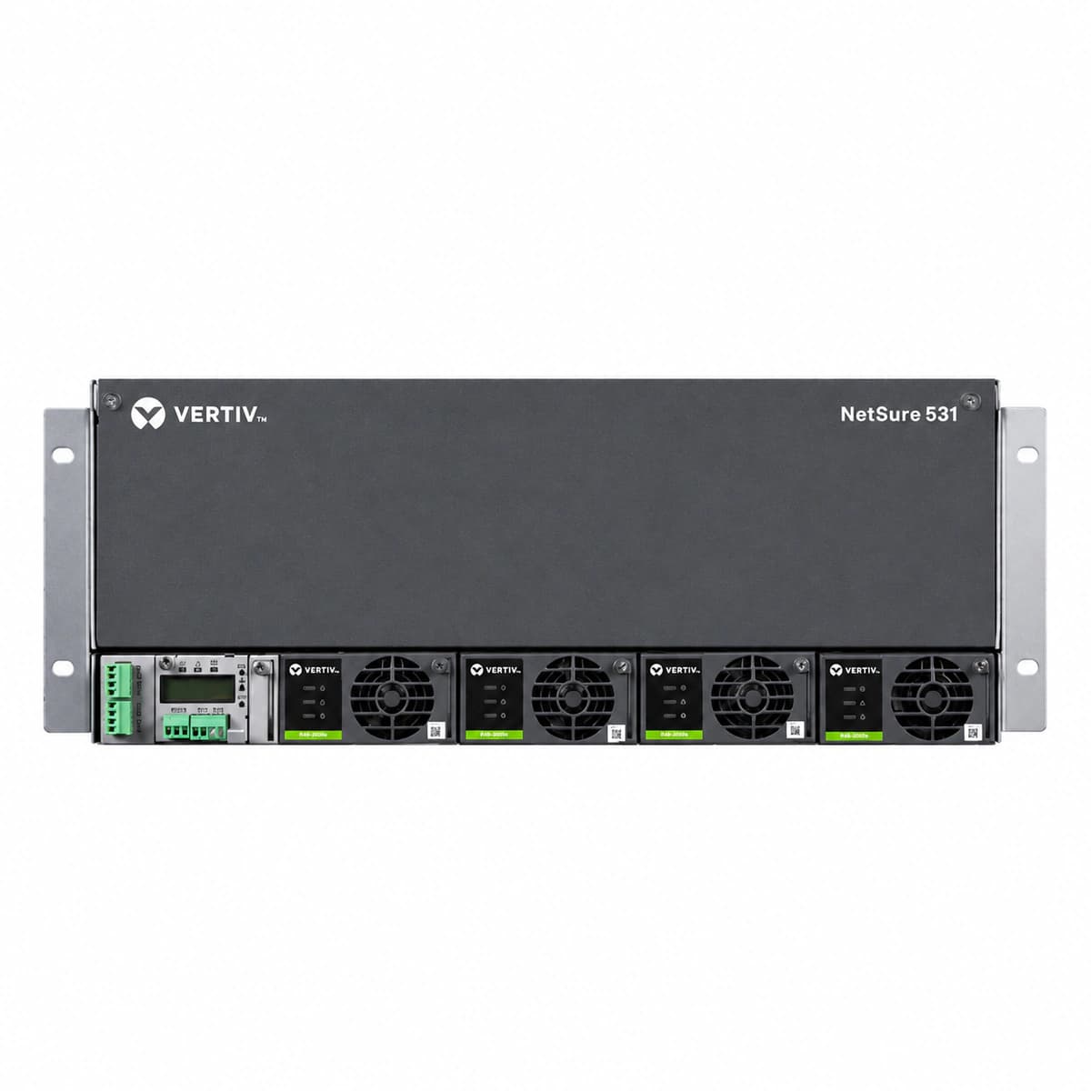
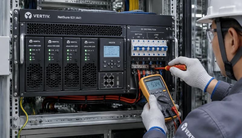
AC_MAINS_FAIL (AC Mains Failure)
Controller ALARM LED solid red, Rectifier Green LED OFF, Rectifier Yellow LED solid ON.
Utility grid power outage, tripped AC input circuit breaker, or phase voltage dropped below 80VAC threshold.
1. Measure phase-to-neutral voltage at the AC input terminal block with a DMM to verify grid availability.
2. Inspect the upstream AC input breaker and SPD surge backup breaker; reset if tripped.
3. If grid power is normal but individual rectifiers report failure, reseat the module and verify connector integrity.
RECT_HVSD (Rectifier Output High Voltage Shutdown)
Faulty rectifier Red FAULT LED solid ON; Green and Yellow LEDs OFF; Controller triggers Critical alarm tone.
Internal PWM feedback circuit failure or active current-share runaway causing DC voltage to exceed the 59.5V hardware protection threshold.
1. Identify the locked rectifier slot number on the controller LCD and record the peak output voltage.
2. Disconnect AC input to the module or unseat it for 60 seconds to fully discharge internal bulk capacitors.
3. Re-insert the module; if it immediately trips back into HVSD lockout, replace the rectifier module.
LLVD_ACT (Load Low Voltage Disconnect Active)
Controller CRITICAL LED solid red, LLVD contactor mechanically open, continuous buzzer alarm.
Prolonged AC mains outage causing deep battery discharge down to disconnection threshold (default 44.0VDC).
1. Connect an emergency generator or restore AC utility to bring rectifiers online and recover -48V bus.
2. Monitor bus voltage rise above reconnect threshold (e.g., 50.0V); verify automatic LLVD contactor reclosure.
3. If contactor fails to pick up automatically, execute manual closure test via controller menu and check coil drive fuse.
CAN_COMM_FAIL (Rectifier CAN Bus Communication Failure)
Rectifier Yellow LED flashing (0.5Hz), Green LED solid ON; Controller MAJOR Yellow LED illuminated.
Damaged backplane CAN interface connector, faulty CAN transceiver inside module, or missing bus termination resistor.
1. Eject the affected rectifier module and inspect gold fingers and backplane mating pins for bend or contamination.
2. Seat the module into a known-good vacant slot to isolate slot backplane wiring from module transceiver failure.
3. Check CAN bus address map in controller; if unassigned and yellow LED keeps blinking, replace the rectifier unit.
RECT_FAN_FAIL (Rectifier Fan Failure)
Rectifier Yellow LED solid ON, Red FAULT LED flashing; Controller registers a MAJOR alarm.
Cooling fan impeller blocked by debris, bearing wear/seizure due to dust accumulation, or loss of tachometer speed feedback signal.
1. Inspect the rectifier front bezel for debris blocking the fan impeller; clear dust using dry compressed air.
2. Check for smooth blade rotation; inspect the fan power and tachometer wire harness connection inside the front assembly.
3. If the fan remains stationary or speed is insufficient causing thermal derating, replace the hot-swappable fan tray assembly.