AC_FAIL (AC Mains Failure / Phase Loss)
Controller Alarm LED solid red; Rectifier Power LED off, Protection LED solid yellow
Commercial AC grid outage, input AC circuit breaker tripped, SPD surge arrestor blown, or phase voltage dropped below undervoltage threshold
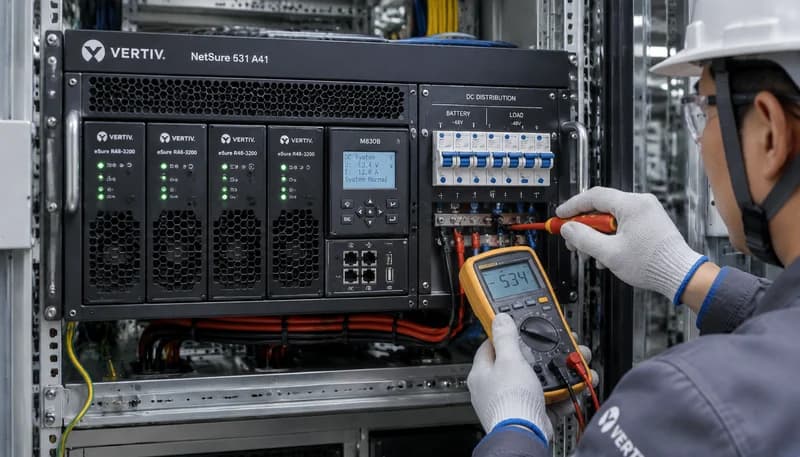
1. Measure AC distribution input terminals with a multimeter to verify phase and neutral voltages are within operational range (85V-300VAC).
2. Inspect the main AC breaker and branch breakers; verify absence of short circuits before resetting.
3. Check the AC SPD status indicator window; replace the surge protection module immediately if red.
RECT_HVSD (Rectifier DC Overvoltage Lockout)
Faulty Rectifier Fault LED solid red; Controller LCD displays Rectifier HVSD alarm
Internal voltage loop component failure, active current share failure, or external surge pushing output voltage above hardware lockout threshold (>59.5VDC)
1. Identify the slot number of the locked-out rectifier via the NCU/controller display.
2. Unlock the handle and pull the faulty module out; wait 1 minute for internal capacitor discharge, then reseat and latch it.
3. If the module trips into red-LED lockout again immediately, the internal circuit is damaged; replace the rectifier module.
DC_LOW_LLVD (DC Bus Undervoltage & LLVD Disconnect)
Controller Alarm LED blinking red; audible buzzer active; LLVD contactor opened
Extended AC outage draining batteries down to disconnect threshold (typically 43.2V-44.0V), total rectifier output loss, or heavy load short
1. Connect an emergency mobile generator to restore AC feed to the NetSure system immediately.
2. Verify that battery circuit breakers are closed and inspect non-priority distribution branches for short circuits.
3. Once AC input is restored and rectifiers raise bus voltage above reconnect threshold, verify that LLVD contactor automatically reconnects.
RECT_FAN_FAIL (Rectifier Fan Fault / Stalled)
Rectifier Protection LED blinking or solid yellow; Controller displays Rectifier Fan Alarm
Rectifier air inlet obstructed by debris/dust, fan bearing mechanical seizure, or fan tachometer PWM/feedback circuit open
1. Inspect the front air intake of the rectifier and clear accumulated dust or obstructions.
2. Extract the module and gently spin the fan blades using an insulated probe to check for mechanical binding or debris.
3. If blades rotate freely but the alarm persists after re-insertion, replace the internal fan assembly or the rectifier module.
COMM_CAN_FAIL (CAN Bus Communication Loss)
Rectifier green Run LED blinking; Controller Alarm LED solid yellow; Controller reports missing/lost modules
Backplane CAN bus signal connector loose/oxidized, module not fully seated in rack, terminating resistor missing/damaged, or controller CAN transceiver failure
1. Verify that the reporting rectifier is fully pushed into the subrack slot and the latch handle is locked firmly.
2. Remove the module and inspect the gold fingers and backplane CAN pins for bent, pushed, or oxidized contacts.
3. Verify the 120-ohm CAN bus terminating resistor; if all subrack rectifiers lose communication simultaneously, restart or replace the controller unit.