Vertiv NetSure 731 A98 2.1m Outdoor Cabinet Equipment information & support
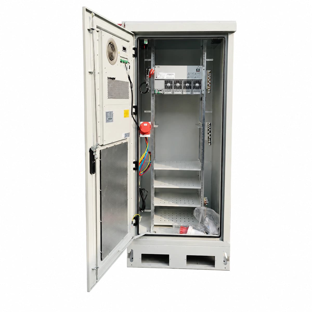
The Vertiv NetSure 731 A98 is a 2.1m high-capacity outdoor telecom DC power cabinet system delivering -48V/600A rated output with IP55 protection, engineered for mission-critical macro stations and extreme environmental installations.
Information below comes from the current product catalogue. Confirm the controller, software version and configuration of the installed equipment separately.
Rectifier Green LED OFF, Yellow LED flashing or Red LED ON; NCU controller Critical Red LED solid
Grid blackout, main AC distribution breaker tripped, AC input voltage below 85VAC threshold, or loose phase wiring.
1. Measure phase-to-phase and phase-to-neutral voltages at the AC input terminal block using a multimeter.
2. Inspect the main AC input breaker and individual rectifier breakers; reset if tripped due to transient surge.
3. Check AC voltage readings and alarm thresholds on the NCU interface; verify the AC sensing cable harness if voltages are normal.
RECT_HVSD (Rectifier Output High Voltage Shutdown)
Faulty Rectifier Red Alarm LED solid ON, Green LED OFF; NCU indicates Major/Critical alarm
Internal PWM loop failure causing output voltage >59.5VDC triggering hardware latch-off, or severe CAN bus noise causing regulation failure.
1. Identify the locked module position via the NCU controller alarm log and note the peak voltage.
2. Disengage the faulty rectifier from the backplane, wait 60 seconds for internal capacitors to discharge, and reinsert.
3. If the red LED relocks immediately upon power-up, the internal hardware is damaged; replace with an identical spare rectifier module.
DC_LOW_DISCONNECT (DC Bus Low Voltage Disconnect / LLVD-BLVD Tripped)
NCU controller Red Alarm LED solid, audible buzzer active; LLVD/BLVD contactor flag shows OPEN
Prolonged AC mains outage drained batteries below protection thresholds (LLVD ~44.0V, BLVD ~42.0V), or contactor coil driver failure.
1. Verify utility status or deploy a mobile diesel generator; measure total battery terminal voltage at the copper busbar.
2. If authorized for emergency telecom recovery, execute 'LVD Manual Reconnect' in the NCU menu to force contactor closure.
3. Upon AC restoration, ensure rectifiers ramp up into boost charge (current limit <= 0.15C10) and verify the LVD automatically latches closed when voltage exceeds 50V.
CAB_OVER_TEMP (Cabinet Internal High Temperature)
Door heat exchanger/air conditioner controller Red/Amber LED ON; NCU temperature value highlighted in Amber/Red
Air filters blocked by debris, internal/external circulation fan rotor seized, door DC aircon compressor fault, or extreme ambient solar load exceeding 55°C.
1. Inspect and clean external air filters and the heat exchanger core fins to eliminate airflow restriction.
2. Trigger the 'Fan Test' routine via NCU to verify RPM feedback on both internal and external cooling circuits; replace any seized fan assembly.
3. Check cabinet door perimeter rubber seals and confirm temperature sensor (PT100/NTC) placement is not directly adjacent to rectifier heatsinks.
SPD cartridge mechanical inspection window turned from Green to RED; NCU Yellow Warning LED ON
Metal Oxide Varistor (MOV) degraded after absorbing high-energy lightning surge, or the auxiliary microswitch signal wiring became loose.
1. Inspect AC and DC SPD blocks to identify which specific phase cartridge has turned red (L1, L2, L3, or N-PE).
2. Switch off the dedicated SPD backup circuit breaker, pull out the blown cartridge, and insert an identical replacement (e.g., Class C 20-40kA rated).
3. Test the dry contact auxiliary terminal loop with a multimeter to verify continuity; confirm that the NCU clears the alarm automatically.
Access Complete Maintenance & Full Alarm Troubleshooting Manual
This page lists high-frequency critical alarm codes commonly encountered in field maintenance. Comprehensive manufacturer troubleshooting matrices, board-level repair guides, detailed electrical schematics, and firmware commissioning manuals are delivered alongside equipment upon formal project procurement, accompanied by dedicated FAE technical support.
Record the nameplate, system model and controller or module model.
02
Keep the alarm details
Record the full alarm text, indicator colour, timing and whether it persists.
03
Describe recent changes
Note recent replacements, software updates or configuration changes.
Record information visible in the existing interface. Electrical measurements, disassembly and replacement should follow the applicable manufacturer's manual and be performed by qualified personnel.
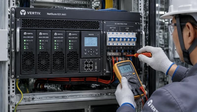
An authoritative engineering manual for the Vertiv / Emerson NetSure 531 A41 series 19-inch 4U telecom embedded DC power subrack. Covers AC/DC distribution terminal schematics, battery and load cabling, M830B / M221S supervisory parameter setup, two-stage LLVD (Load Low Voltage Disconnect) and BLVD (Battery Low Voltage Disconnect) threshold programming, and full on-site commissioning procedures.