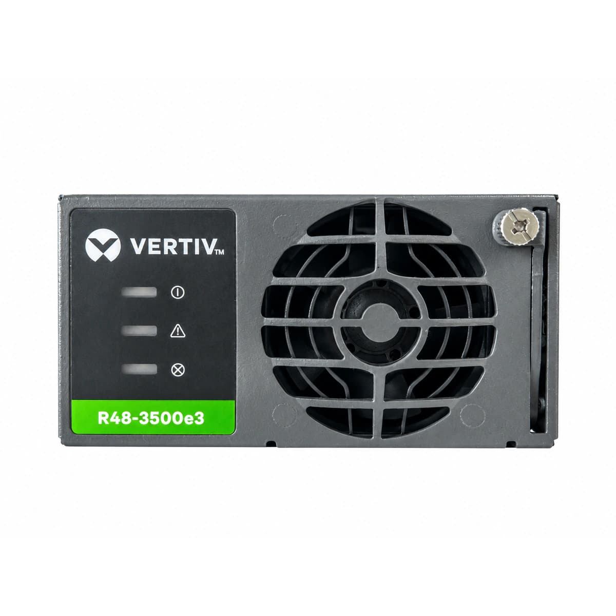
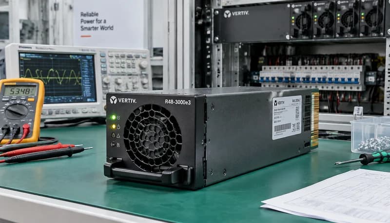
The Vertiv R48-3500E3 is an ultra-high-efficiency switchmode AC-DC rectifier module engineered for high-density telecom sites and enterprise data centers. Featuring advanced full-bridge resonant topology and digital DSP control, it supports an 85V to 300V AC input, delivering 3500W nominal output at -48V DC with up to 96.5% titanium-grade efficiency, autonomous active load sharing, and hot-swappable connectivity.
Information below comes from the current product catalogue. Confirm the controller, software version and configuration of the installed equipment separately.
Rated Output Power
3500W High Power Output
Rated Output Current
67.3A (Max Current at 58V DC)
Power Conversion Efficiency
≥ 96.2%
Output Power Factor PF
≥ 0.99 (Ultra-Low Harmonic Distortion THD<5%)
Cooling Architecture
Built-in Temperature Controlled Variable Fan (Low Noise)
Green LED (Power) Off, Yellow LED (Protection) Solid On
Utility grid outage, AC input voltage <85VAC or >305VAC, tripped AC input breaker, or loose input terminal connection.
1. Measure AC input voltage across L and N terminals at the backplane using a True-RMS DMM; verify it is within 85VAC–300VAC.
2. Inspect the upstream AC input breaker and SPD status for tripping or physical damage.
3. Reseat the module firmly to verify backplane connector engagement; replace the rectifier if the condition persists with normal input.
Module output exceeded hardware HVSD threshold (58.5VDC–60.0VDC), internal voltage regulation circuit failed, or external backfeed occurred.
1. Disconnect the locked module, wait 3 minutes for capacitor discharge until all LEDs extinguish, then re-insert to test for reset.
2. If it resets normally, check the controller (e.g., M830B/NCU) DC overvoltage threshold settings for misconfiguration.
3. If the module instantly locks out again with red LED on, internal MOSFET/rectifier circuit is damaged; replace the module.
Yellow LED Flashing (Derating) or Yellow LED Solid On with Green LED Off (Shutdown)
Ambient temperature exceeding +55°C (thermal derating range, >+65°C causes shutdown), clogged air filter, restricted airflow, or heat sink dust buildup.
1. Check equipment room HVAC operation and inlet air temperature; verify ambient intake is below +45°C.
2. Clean the cabinet air filters and the front perforated ventilation holes of the rectifier module.
3. Verify whether the internal fan ramps up to full speed; if temperature is normal and fan runs properly, internal NTC thermistor has failed; replace module.
FAN_FAIL (Fan Locked-Rotor / Fan Failure)
Red LED (Fault) Flashing (0.5Hz–1Hz), Yellow LED (Protection) Solid On
Fan blades jammed by debris or bearing wear-out, loss of tachometer speed feedback signal, or failed internal fan drive circuit.
1. Visually inspect the front panel fan grille to ensure no cables or debris are obstructing the impeller.
2. Disconnect the module and rotate the blades manually to check for smooth mechanical rotation without friction.
3. If mechanically free but the fan fails to spin or the red LED continues blinking upon power-up, replace the fan assembly or the rectifier module.
CAN_COMM_FAIL (CAN-bus Communication Loss & Current Share Error)
Green LED (Power) Solid On, Yellow LED (Protection) Slow Flashing (0.5Hz)
CAN-bus communication link lost between rectifier and system controller, module ID address conflict, bent/oxidized connector pins, or unshared load current exceeding ±10%.
1. Access the system controller UI to verify whether the rectifier is recognized and its communication status.
2. Extract the module and inspect the rear blind-mate connector (CAN-H, CAN-L pins) for bent pins, dust, or corrosion; clean with isopropyl alcohol and reseat.
3. If all rectifiers in the shelf report CAN loss, measure CAN-bus termination resistance across lines (nominal ~60Ω with power off) to isolate an open bus or faulty controller interface.
Access Complete Maintenance & Full Alarm Troubleshooting Manual
This page lists high-frequency critical alarm codes commonly encountered in field maintenance. Comprehensive manufacturer troubleshooting matrices, board-level repair guides, detailed electrical schematics, and firmware commissioning manuals are delivered alongside equipment upon formal project procurement, accompanied by dedicated FAE technical support.
Record the nameplate, system model and controller or module model.
02
Keep the alarm details
Record the full alarm text, indicator colour, timing and whether it persists.
03
Describe recent changes
Note recent replacements, software updates or configuration changes.
Record information visible in the existing interface. Electrical measurements, disassembly and replacement should follow the applicable manufacturer's manual and be performed by qualified personnel.
An exhaustive engineering practical guide for Vertiv / Emerson eSure R48-3000e3, R48-3500e3, and R48-2000e3 high-frequency switchmode rectifier modules, detailing backplane gold-finger connector pinouts, standalone bench startup wiring, CAN bus digital voltage tuning frames, active autonomous current sharing, and systematic resolution of five critical field alarm codes.