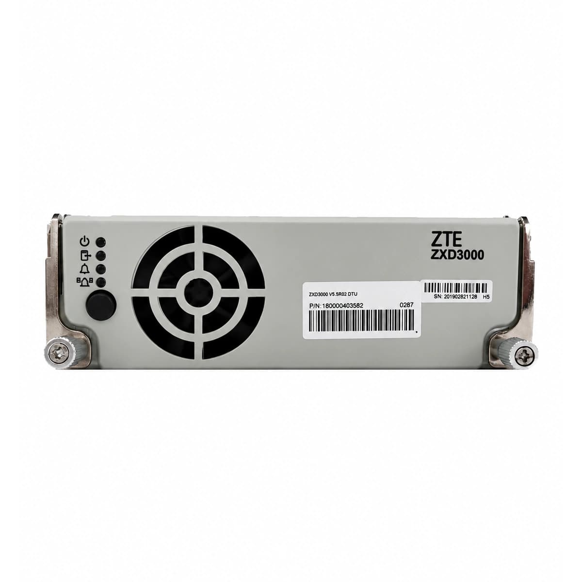
The ZTE ZXD3000 V5.5 is a high-density, hot-swappable 3000W single-phase telecom switch-mode rectifier utilizing advanced soft-switching APFC topology and an isolated LLC resonant stage. It accepts a wide AC input range of 85V~295V AC to deliver a regulated nominal -48V DC (50A continuous) with an industry-leading peak efficiency of ≥ 96.3%, engineered for central telecom offices and wireless base stations.
Information below comes from the current product catalogue. Confirm the controller, software version and configuration of the installed equipment separately.
Power LED (Green) OFF, Alarm LED (Yellow) Solid ON, Fault LED (Red) OFF
Utility grid blackout, AC input voltage < 80 VAC threshold, input circuit breaker tripped, or loose terminal lugs on AC distribution busbar
1. Measure AC voltage across L and N pins at the subrack backplane using a multimeter to confirm utility voltage is within operating range (85–295 VAC).
2. Inspect the upstream rectifier branch circuit breaker in the ACDU; verify there are no short circuits, then reset breaker.
3. Inspect rear floating connector pins for arcing or corrosion, re-seat rectifier module firmly, and lock insertion lever.
OUT_OVP (DC Output Overvoltage Lockout / HVSD)
Fault LED (Red) Solid ON, Power LED (Green) OFF, Alarm LED (Yellow) OFF
Internal PWM regulation loop malfunction driving output voltage above hardware threshold (59.5V ±0.5V), or corrupted CSU control parameters triggering high-voltage shutdown
1. Unseat the module, remove AC power, wait 3 minutes for bus capacitors to discharge until all LEDs extinguish, then re-insert to perform a hard reset.
2. Verify float/equalize overvoltage parameters on the Central Supervisory Unit (CSU) (default 58.5V) and ensure no CAN bus address clashes.
3. If Red LED latches on immediately after re-insertion, internal secondary feedback or power MOSFETs are shorted; replace the rectifier module.
Derating: Green Solid ON + Yellow Blinking (0.5 Hz); Shutdown: Green OFF + Yellow Solid ON + Red OFF
Shelter ambient temperature exceeding +55°C, front air intake dust filter blocked, rear exhaust airflow obstructed, or degraded internal NTC thermistor
1. Inspect shelter HVAC/air conditioning systems and verify ambient ambient temperature returns to standard operating range (+15°C to +30°C).
2. Remove front intake filter, clean accumulated lint and debris using dry compressed air, and clear rear exhaust clearance.
3. Check module internal temperature reading via CSU; if reported value deviates >10°C from actual heatsink infrared reading, replace the rectifier module.
FAN_FAIL (Cooling Fan Stall / Tachometer Loss)
Fault LED (Red) Blinking (1 Hz), Alarm LED (Yellow) Solid ON, Power LED (Green) ON
Cooling fan bearing seized by foreign objects, defective PWM speed control circuit, loss of Hall sensor tachometer feedback, or disconnected internal fan harness
1. Visually inspect fan blades through the front panel grille for physical obstructions, cables, or foreign matter.
2. Spin the blades manually (with power unseated) to test bearing smoothness; excessive resistance indicates bearing failure.
3. Disconnect module, inspect internal 4-pin fan connector for secure seating; if fan fails to spin up upon power restore, replace the fan assembly or rectifier.
COMM_FAIL (CAN-Bus Communication Loss / Autonomous Mode)
Power LED (Green) Solid ON, Alarm LED (Yellow) Blinking (0.5 Hz), Fault LED (Red) OFF
CAN bus wiring disconnected between rectifier and CSU, corrupted backplane pin seating, missing 120-ohm bus termination resistor, or failed module CAN transceiver IC
1. Check the CSU status LEDs to confirm controller is operational and correctly polling rectifier module IDs.
2. Eject the module, clean rear connector pins (specifically CAN_H and CAN_L contacts) with isopropyl alcohol, and firmly re-seat.
3. Measure CAN bus resistance with power unseated across CAN_H and CAN_L (nominal is ~60 ohms across the parallel 120-ohm terminators); if fault follows module to other slots, replace rectifier.
Access Complete Maintenance & Full Alarm Troubleshooting Manual
This page lists high-frequency critical alarm codes commonly encountered in field maintenance. Comprehensive manufacturer troubleshooting matrices, board-level repair guides, detailed electrical schematics, and firmware commissioning manuals are delivered alongside equipment upon formal project procurement, accompanied by dedicated FAE technical support.
Record the nameplate, system model and controller or module model.
02
Keep the alarm details
Record the full alarm text, indicator colour, timing and whether it persists.
03
Describe recent changes
Note recent replacements, software updates or configuration changes.
Record information visible in the existing interface. Electrical measurements, disassembly and replacement should follow the applicable manufacturer's manual and be performed by qualified personnel.
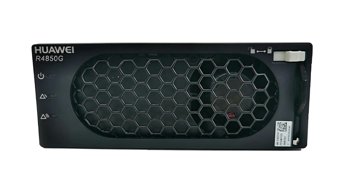
A comprehensive technical breakdown of 48V/50A rectifier modules (Huawei R4850G2 / ETP48400 architecture), covering blind-mate connector pinouts, standalone startup jumpers, CAN 2.0B hex commands for CV/CC adjustment, and active current sharing troubleshooting.