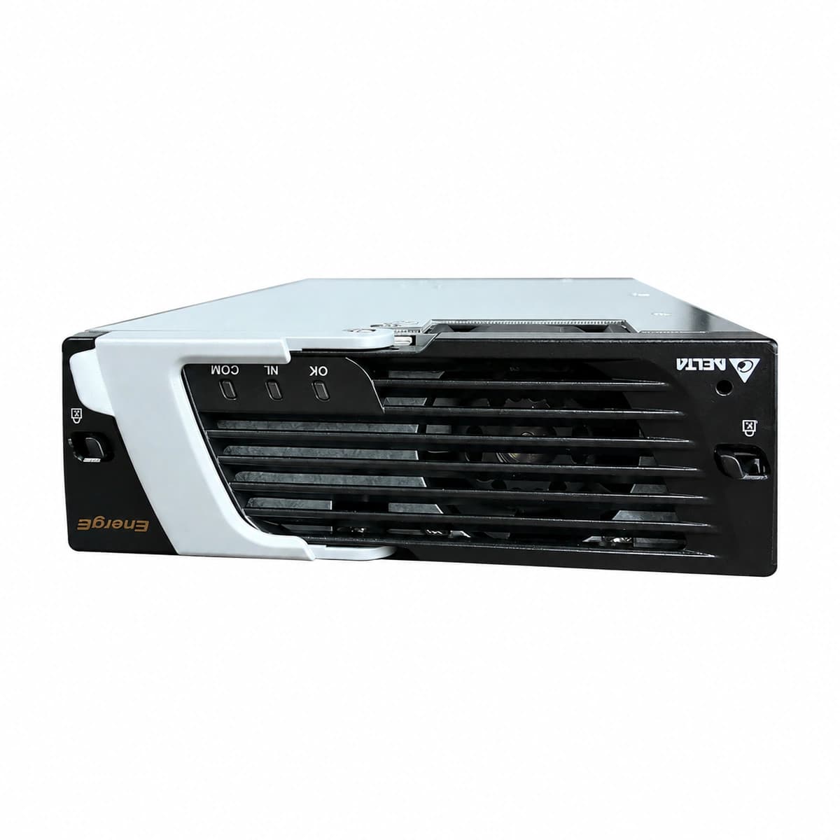
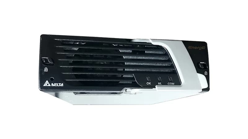
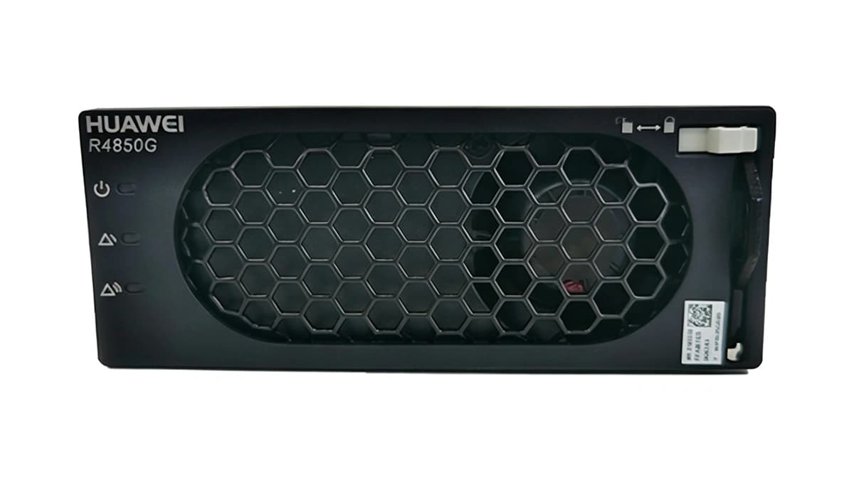
AC_IN_FAIL (AC Input Out of Range/Failure)
Green Run LED OFF, Amber/Yellow Protection LED solid ON
Mains blackout; AC voltage below 80VAC or above 300VAC; input breaker tripped or loose connection on AC terminal block.
1. Measure AC input voltage across L-N on the module backplane using a True-RMS multimeter.
2. Verify that the dedicated AC input MCB in the distribution cabinet is closed.
3. If AC voltage is within 85-300VAC and MCB is closed, re-seat the rectifier module; replace the module if the alarm persists.
DC_OVP / HVSD (DC Overvoltage High Voltage Shutdown)
Red Alarm LED solid ON, Green Run LED OFF
Internal voltage control loop failure; invalid voltage setpoint from controller; failure of internal regulation components causing output voltage to exceed the 59.5V hardware limit.
1. Check the float/boost voltage configuration on the system controller (CSU) to verify it does not exceed 58.0VDC.
2. Unseat the fault rectifier module and wait 3 minutes to discharge internal bus capacitors, then re-insert to reset the HVSD latch.
3. If the red Alarm LED turns on immediately upon restart, replace the defective module.
OTP (Over-Temperature Protection / Derating)
Amber Protection LED solid or blinking slowly; Green Run LED OFF if shutdown occurs
Ambient temperature exceeds 55°C; cabinet air filter clogged; restricted airflow/blocked chassis vents; internal heatsink temperature sensor fault.
1. Inspect telecom shelter/room air conditioning; ensure inlet temperature is between 20°C and 25°C.
2. Clean or replace cabinet dust filters and remove obstructions from module inlet/exhaust grills.
3. Allow the rectifier to cool down; it will automatically resume operation when the heatsink temperature drops below the safe threshold (<75°C). Replace the unit if false alarms persist.
FAN_FAIL (Fan Stalled / Tachometer Failure)
Red Alarm LED ON or Amber Protection LED flashing rapidly
Rectifier cooling fan mechanically obstructed; bearing worn or seized; fan tachometer feedback circuit defective or power cable disconnected.
1. Visually check the front fan assembly with a flashlight to verify there is no physical blockage.
2. Withdraw the module and verify internal fan harness connectors are seated securely.
3. Re-insert the module and observe if the fan spins during power-on self-test; replace fan assembly or the entire rectifier if it fails to spin.
CAN_COMM_FAIL (CAN Bus Communication Loss / Current Share Fault)
Green Run LED solid ON, Amber Protection LED blinking (1Hz)
Gold-finger connector pin oxidation or poor contact on the backplane; CAN bus termination resistor open; central controller (CSU) port fault or module address conflict.
1. Remove the module and inspect backplane gold-finger pins for damage, dust, or bent contacts; clean and reseat firmly with latch locked.
2. Check the system controller (CSU) rectifier status list to identify address conflicts; initiate a bus re-scan if supported.
3. Verify the 120Ω CAN termination resistor on the power shelf; replace the rectifier module if its internal transceiver has failed while other modules communicate properly.