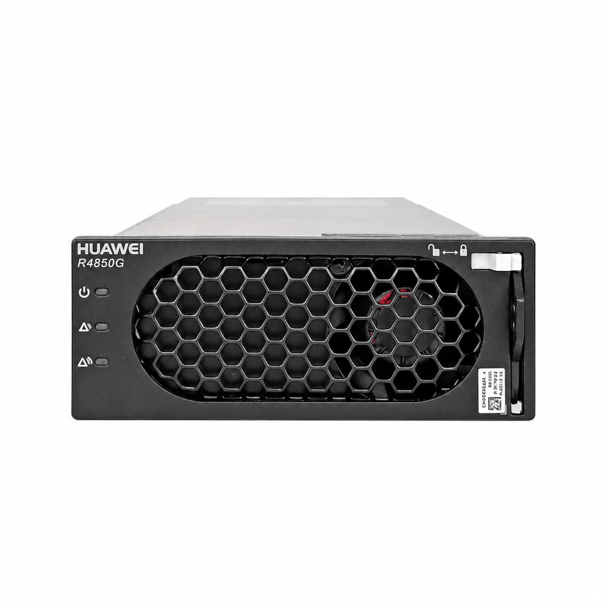
AC_IN_FAIL (AC Mains Input Abnormal/Failure)
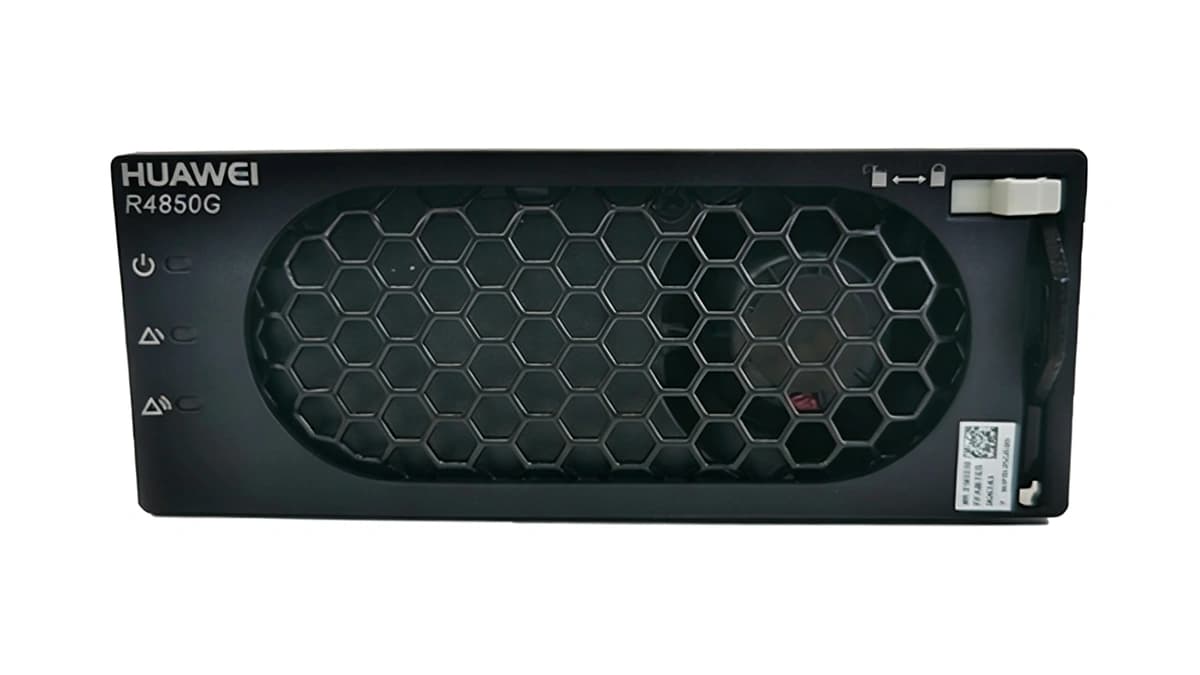
Power LED (Green) off, Alarm LED (Yellow) solid on
AC mains power outage, or grid voltage exceeds rectifier operating threshold (85V AC - 300V AC); input circuit breaker tripped or connector loose
1. Measure AC input voltage between L and N at the slot backplane using a DMM to verify it is within 85V AC - 300V AC.
2. Inspect the upstream AC input MCB in the PDU to verify if it has tripped; clear any fault and reset breaker.
3. Reseat the rectifier to ensure backplane connector engagement; if input voltage is normal and alarm persists, replace the R4850G2 module.
OUT_OVP (DC Output Overvoltage Lockout)
Fault LED (Red) solid on, Power LED (Green) off
Internal PWM loop failure or output voltage feedback circuit failure, causing output to exceed hardware threshold (59.5V DC ± 0.5V DC) triggering latching shutdown
1. Remove the rectifier from the subrack, wait 1 minute to discharge internal bulk capacitors, then reinsert to test soft-start.
2. Verify the system float/boost voltage parameters in the SMU controller to ensure they are not configured improperly.
3. If the red LED turns solid on immediately after reinsertion, the internal power stage or control board is damaged; replace the R4850G2.
OVER_TEMP (Rectifier Over-Temperature Derating/Shutdown)
Alarm LED (Yellow) solid on; Power LED (Green) off if over-temp shutdown point reached
Air intake ambient temperature exceeds 55°C due to HVAC failure; air intake/dust mesh severely clogged; internal heatsink thermistor exceeds safety threshold
1. Inspect site air conditioning to restore ambient intake air temperature within rated operating range (-40°C to +55°C).
2. Clean the front panel ventilation grille and subrack dust filters to ensure unimpeded front-to-rear airflow.
3. If ambient temperature and airflow are normal and fan spins freely but over-temperature persists, replace the module due to degraded thermal sensors.
FAN_FAIL (Fan Locked-Rotor/Drive Fault)
Fault LED (Red) blinking (0.5 Hz), Alarm LED (Yellow) solid on
Foreign object jamming internal BLDC cooling fan rotor; fan wiring harness disconnected or tachometer pin broken; bearing wear causing fan RPM below critical threshold
1. Visually inspect the front fan blades for cable ties, dust clots, or foreign debris; power off and clear blockages.
2. Reseat the module and observe whether the fan spins, vibrates, or generates abnormal acoustic noise during initial power-on self-test.
3. If no mechanical blockage exists but the fan fails to spin or tachometer alarm persists, replace the R4850G2 rectifier.
COMM_FAIL (CAN Bus Communication Lost)
Alarm LED (Yellow) blinking slowly (0.5 Hz), Power LED (Green) solid on
Poor contact on CAN bus backplane pins between rectifier and SMU (e.g. SMU02B/SMU02C); backplane trace damaged; module operating in autonomous standalone fallback mode (default 53.5V DC)
1. Check the monitoring unit (SMU) status to verify it is operational and not frozen.
2. Reseat the rectifier module; inspect the backplane CAN_H and CAN_L connector pins for oxidation, bent contacts, or contamination, and clean if necessary.
3. Swap the module into a known-good subrack slot: if communication restores, troubleshoot the original subrack slot; if the fault persists, replace the R4850G2 module.