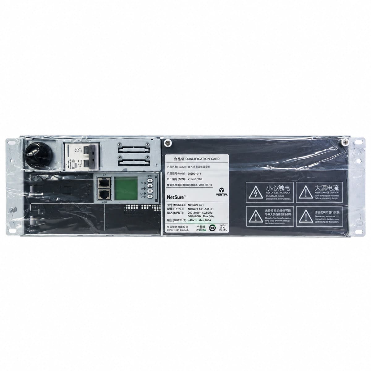
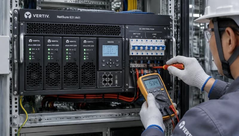
AC_FAIL (AC Mains Failure / Abnormal)
Controller Alarm LED Red solid; Rectifier Run LED (Green) Off, Protection LED (Yellow) Solid
Utility grid blackout, upstream AC input circuit breaker tripped, or phase voltage dropped below 80VAC operating threshold
1. Measure true AC voltage across L/N input terminals using a true-RMS multimeter.
2. Inspect upstream distribution breakers and the AC Surge Protective Device (SPD) for trip or failure.
3. If mains power is within spec, reseat the rectifiers and toggle the AC branch breaker.
REC_HVSD (Rectifier DC Overvoltage Lockout)
Rectifier Alarm LED Red solid, Run LED Green Off; Controller LCD displays slot-specific HVSD
Internal voltage control feedback failure inside rectifier causing DC output to exceed 59.5V threshold, triggering hardware latching shutdown
1. Identify the faulty rectifier slot number via controller LCD/web GUI.
2. Extract the module, wait 60 seconds for bus capacitors to discharge, then reinsert to reset the latch.
3. If the module trips into HVSD immediately upon re-engagement, replace the defective rectifier unit.
BLVD_ACT (Battery Low Voltage Disconnect Active)
Controller Alarm LED Red flashing, audible buzzer active; Battery contactor status shows Open
Prolonged AC grid outage caused battery bank to deplete below BLVD threshold (typically 43.2V), forcing contactor open to prevent cell destruction
1. Deploy an emergency mobile diesel generator to restore AC mains power to the system.
2. Once AC is restored, rectifiers automatically boot and raise DC bus voltage until the contactor re-closes.
3. Verify in controller settings that battery charge current limit is active (nominal 0.1C10) to prevent thermal runaway.
REC_COMM_FAIL (Rectifier CAN Bus Comm Loss)
Controller Alarm LED Yellow/Amber solid; Affected rectifier Protection LED (Yellow) flashes at 0.5Hz
Loose backplane CAN ribbon cable, oxidized gold-finger connector pins, address collision, or damaged CAN transceiver chip inside rectifier
1. Eject the rectifier, inspect rear gold-finger pins for debris/bent pins, and firmly reseat with locking latch.
2. Verify the CAN ribbon cable linking the controller to the subrack backplane is fully seated.
3. Swap the module into an adjacent known-good slot; if fault follows the module, replace the rectifier.
FAN_FAIL (Rectifier Fan Fault / Stalled)
Rectifier Protection LED (Yellow) Solid or fast flash; Module enters thermal output derating mode
Front grille dust blockage, mechanical bearing seizure, or failure of the internal fan tachometer/PWM circuitry
1. Visually check front intake grille and impeller blades for debris or cable interference.
2. Blow out accumulated dust with dry compressed air; verify fan blades rotate freely by hand.
3. If fan remains stalled or tachometer failure persists, replace the fan tray assembly or the rectifier unit.