Vertiv / DC Power Systems (-48V)

R48-1800A Equipment information & support

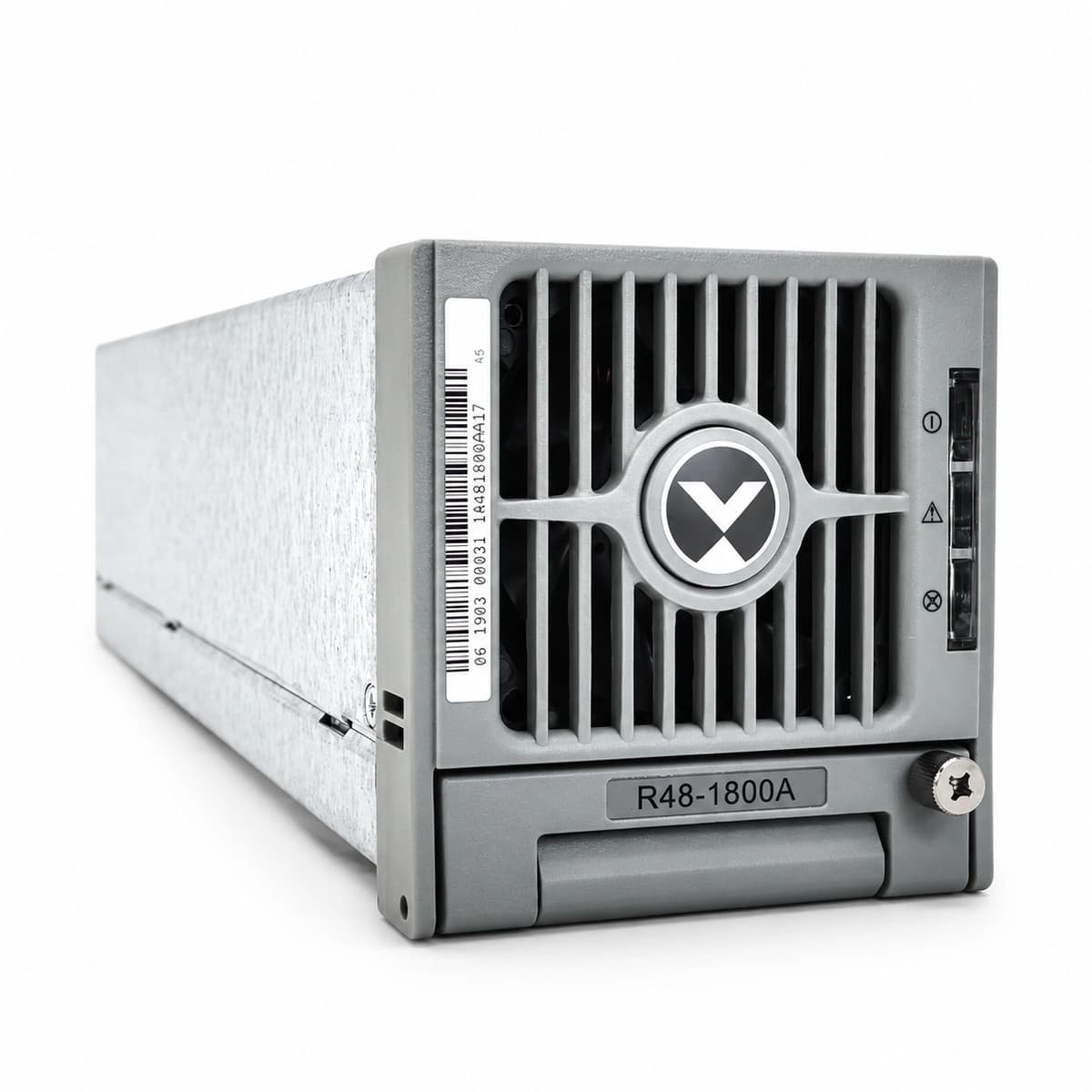
The Vertiv R48-1800A is a carrier-grade, highly reliable, and compact switch-mode rectifier module engineered for telecommunications and industrial DC power plants. Delivering a nominal output of -48V DC (adjustable from -42V to -58V DC) with a maximum current of 37.5A and 1800W rated power, it operates across an ultra-wide AC input range of 85V AC to 290V AC to ensure uninterrupted power in demanding utility conditions.

Equipment information

Brand
Vertiv
Equipment model
R48-1800A
Equipment type
DC Power Systems (-48V)
Controller / software version
Confirm against the installed equipment
View full product specifications
Vertiv R48-1800A Genuine Telecom Hardware Shot 1

Information below comes from the current product catalogue. Confirm the controller, software version and configuration of the installed equipment separately.

Rated Output Voltage
-48VDC (-42V ~ -58V)
Rated Output Power
1800W
Maximum Output Current
37.5A
AC Input Voltage
85V AC ~ 290V AC
Maximum Efficiency
≥ 92.5%
Operating Temperature Range
-40°C ~ +70°C

Alarms & troubleshooting

MAINS_FAIL / AC_POWER_LOSS (Utility Grid Failure / Total AC Ingress Loss)
Cabinet controller red ALARM LED solid with acoustic buzzer; system seamlessly transitions to battery discharge.
Grid utility failure, upstream transformer trip, automatic transfer switch (ATS) fault, or tripped main breaker.
1. Verify battery discharge current and remaining backup runtime on controller; 2. Start backup diesel generator (DG) and verify ATS transfer; 3. Measure incoming 3-phase line voltage and frequency stability; 4. Upon grid restoration, verify rectifiers soft-start and engage battery recharge.
LLVD_TRIP / LOAD_SHEDDING (Load Low Voltage Disconnect Tripped)
Controller LCD triggers LLVD alarm; LLVD contactor mechanically opens; secondary load branches de-energized.
Prolonged mains outage discharging batteries to protection threshold (typically 44.0VDC). System automatically sheds secondary loads to preserve core communications.
1. Confirm critical core branches (BLVD circuit) remain energized and protected; 2. Dispatch emergency mobile power generation cart to site; 3. Upon grid recovery, monitor DC bus voltage ramp above re-engagement threshold (48.0VDC); 4. Verify LLVD contactor re-closes and secondary equipment boots normally.
SPD_FAIL / SURGE_ARRESTOR (Surge Protective Device Degradation / Tripped)
Controller registers SPD alarm; SPD module inspection window turns from Green to Red; alarm dry contact closes.
Site subjected to lightning surge strike or sustained overvoltage, causing MOV thermal breakdown and disconnect.
1. Inspect SPD indicator flags (red flag confirms blown cartridge); 2. Check SPD dedicated backup fuse or circuit breaker; 3. Open SPD isolation switch, extract damaged plug-in cartridge; 4. Replace with genuine replacement cartridge matching rating (20kA/40kA); 5. Close circuit, verify green status flag and alarm self-clearing.

Access Complete Maintenance & Full Alarm Troubleshooting Manual

This page lists high-frequency critical alarm codes commonly encountered in field maintenance. Comprehensive manufacturer troubleshooting matrices, board-level repair guides, detailed electrical schematics, and firmware commissioning manuals are delivered alongside equipment upon formal project procurement, accompanied by dedicated FAE technical support.

Share on-site information

  1. 01

    Identify the exact model

    Record the nameplate, system model and controller or module model.

  2. 02

    Keep the alarm details

    Record the full alarm text, indicator colour, timing and whether it persists.

  3. 03

    Describe recent changes

    Note recent replacements, software updates or configuration changes.

Record information visible in the existing interface. Electrical measurements, disassembly and replacement should follow the applicable manufacturer's manual and be performed by qualified personnel.

Your model and these details will be added to the enquiry form for you to review before sending.

Related technical articles

Technical articles

Vertiv eSure R48 Rectifier Module Pinout, CAN Bus Voltage Tuning, and Troubleshooting Field Guide

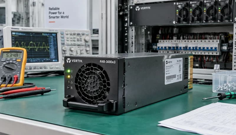
An exhaustive engineering practical guide for Vertiv / Emerson eSure R48-3000e3, R48-3500e3, and R48-2000e3 high-frequency switchmode rectifier modules, detailing backplane gold-finger connector pinouts, standalone bench startup wiring, CAN bus digital voltage tuning frames, active autonomous current sharing, and systematic resolution of five critical field alarm codes.

View all articles

Need a replacement module or supporting equipment?

Confirm the full model, system configuration and compatibility requirements before enquiring about suitable products.

Ask about suitable products

Have a model and an on-site issue?

Share the exact model, alarm text and observed symptoms to help identify relevant information and compatibility requirements.

Request technical support