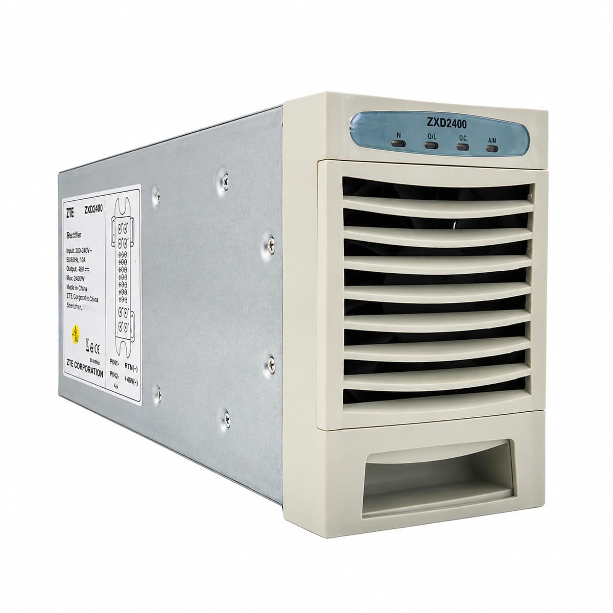
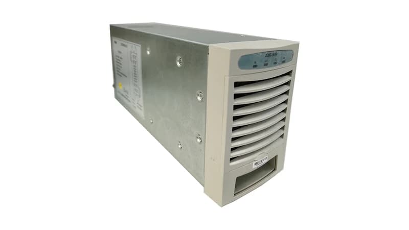
Information below comes from the current product catalogue. Confirm the controller, software version and configuration of the installed equipment separately.
Power LED (Green) OFF, Alarm LED (Yellow) Solid ON
Mains grid blackout, AC input voltage <80VAC or >300VAC, upstream AC circuit breaker tripped, or loose input terminal connection.
1. Measure AC input voltage on the backplane slot using a digital multimeter; verify phase voltage is between 80VAC and 300VAC. 2. Inspect and verify the upstream AC circuit breaker is fully closed and not tripped. 3. Reseat the ZXD2400 rectifier module firmly, inspect slot connector pins for arcing or corrosion, and secure the latch.
OUT_OVP (DC Output Overvoltage Lockout)
Fault LED (Red) Solid ON, Power LED (Green) OFF
Internal PWM loop regulation failure, auxiliary power issue, or feedback sampling circuit failure causing output voltage to exceed 58.5V-60V threshold, triggering hardware latch-off.
1. Extract the faulty module and wait 3 minutes to allow DC-link capacitors to fully discharge, then reinsert to reset the hardware lockout. 2. If the Red Fault LED immediately illuminates upon power-up with 0V output, confirm hardware latch-off. 3. Replace the defective ZXD2400 module immediately if internal power MOSFET or control circuitry is damaged; do not attempt forced operation.
MOD_OTP (Module Over-Temperature Protection)
Alarm LED (Yellow) Solid ON; Fault LED (Red) ON if thermal shutdown limit is reached
Ambient site temperature exceeding +55°C, clogged air inlet dust filter, blocked heatsink airflow tunnel, or drifted internal NTC temperature sensor.
1. Inspect site HVAC cooling and ensure air intake temperature is within the standard 25°C to 35°C range. 2. Clean cabinet front-door dust filters and the air inlet louvers on the rectifier front panel. 3. Remove the module, blow out accumulated dust from the heatsink channels using dry compressed air, reseat the unit, and verify that temperature drops below derating limits.
FAN_FAIL (Cooling Fan Stall/Failure)
Alarm LED (Yellow) Blinking (0.5Hz-1Hz) or Solid ON
Fan blades physically obstructed, fan auxiliary power supply open circuit, tachometer (Hall sensor) feedback line disconnected, or bearing wear resulting in low RPM.
1. Visually check the exhaust vent on the rear/front of the module to verify if the fan is spinning freely or blocked by cabling/debris. 2. Remove the module from power and manually rotate the fan blades with a non-metallic probe to check for bearing resistance. 3. If the fan does not spin or speed feedback remains missing after clearing obstructions, replace the fan sub-assembly or replace the ZXD2400 module.
COMM_FAIL (CAN Communication Loss & Current Share Fault)
Alarm LED (Yellow) Slow Blinking (0.5Hz), Power LED (Green) Solid ON
CAN bus physical link broken between rectifier and Central Supervision Unit (CSU), module CAN address ID conflict, missing 120-ohm termination resistor, or backplane connector pin oxidation causing loss of autonomous current sharing.
1. Access the CSU (Central Supervision Unit) interface, verify rectifier slot addressing, and check for module communication timeouts or address collisions. 2. Unseat the rectifier, inspect the backplane CAN pins for bent or oxidized contacts, clean with electrical contact cleaner, and reseat. 3. Measure line resistance between CAN_H and CAN_L with system unpowered (nominal ~60 ohms across two parallel 120-ohm resistors); replace the ZXD2400 if the internal CAN transceiver is defective.
Access Complete Maintenance & Full Alarm Troubleshooting Manual
This page lists high-frequency critical alarm codes commonly encountered in field maintenance. Comprehensive manufacturer troubleshooting matrices, board-level repair guides, detailed electrical schematics, and firmware commissioning manuals are delivered alongside equipment upon formal project procurement, accompanied by dedicated FAE technical support.
Record the nameplate, system model and controller or module model.
02
Keep the alarm details
Record the full alarm text, indicator colour, timing and whether it persists.
03
Describe recent changes
Note recent replacements, software updates or configuration changes.
Record information visible in the existing interface. Electrical measurements, disassembly and replacement should follow the applicable manufacturer's manual and be performed by qualified personnel.
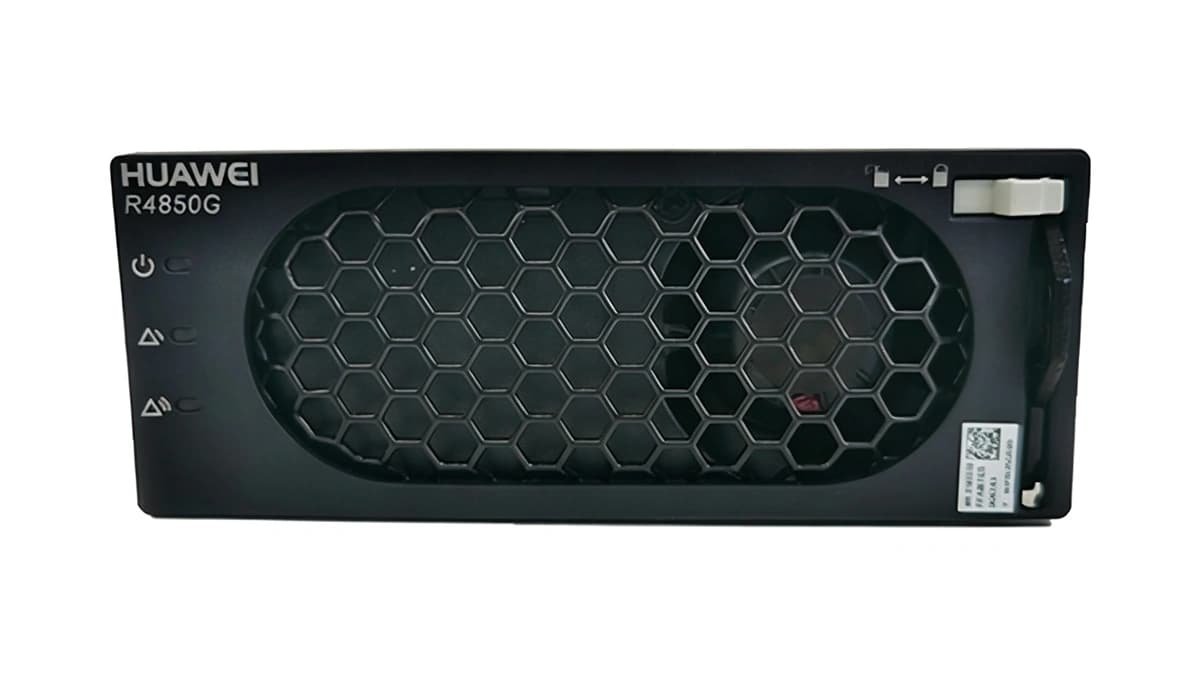
A comprehensive technical breakdown of 48V/50A rectifier modules (Huawei R4850G2 / ETP48400 architecture), covering blind-mate connector pinouts, standalone startup jumpers, CAN 2.0B hex commands for CV/CC adjustment, and active current sharing troubleshooting.