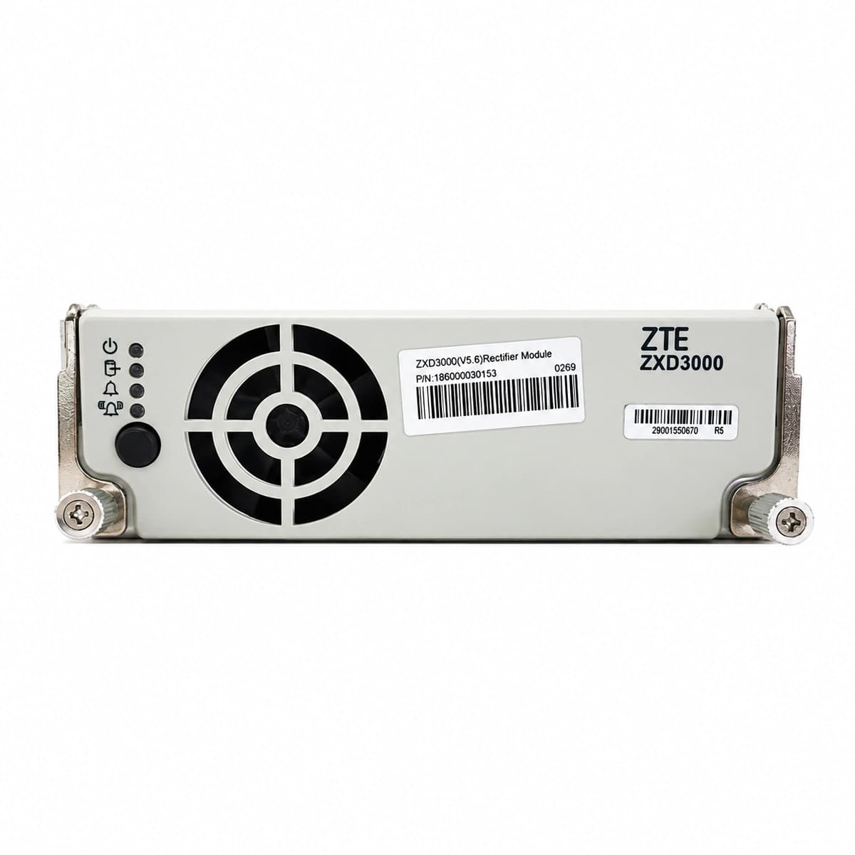
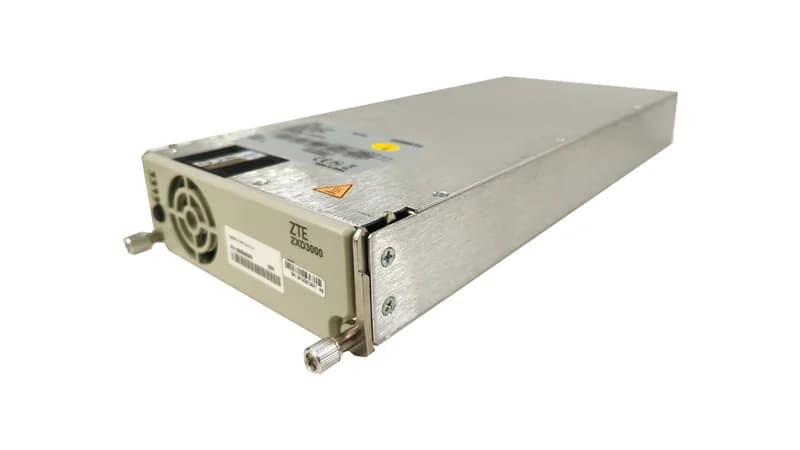
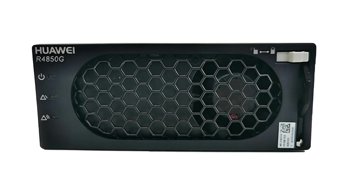
Information below comes from the current product catalogue. Confirm the controller, software version and configuration of the installed equipment separately.
RUN LED (Green) OFF, FAULT LED (Red) or ALM LED (Yellow) solid ON
Mains utility outage, AC input breaker tripped, AC phase voltage below 80 VAC or above 300 VAC threshold, or loose rear AC connector pins
1. Measure AC input L/N voltage with a DMM to confirm it is within 85 VAC to 295 VAC operating range.
2. Verify that the rectifier branch MCB in the AC distribution unit (ACDU) is closed and not tripped.
3. Pull out module and inspect rear blind-mate blind connectors for signs of arcing, burn marks, or bent pins.
4. If AC voltage and breaker are normal and reseating fails, replace the rectifier module.
DC_OVP (DC Output Overvoltage Lockout)
FAULT LED (Red) solid ON, RUN LED (Green) OFF
Internal PWM regulation loop failure, supervisory unit overvoltage threshold misconfiguration, or external surge pushing output voltage past hardware latch limit (≥59.5V–60V)
1. Pull out the alarming rectifier module; measure DC bus voltage with a DMM to ensure float/boost is normal (48V–56.4V).
2. Check the DC overvoltage setpoint on the CSU/monitoring unit (typically 58.5V–59.0V).
3. Power down the module, wait 3 minutes for bus capacitors to discharge completely, then re-insert and re-apply AC power.
4. If the module triggers hardware red LED lockout immediately upon powering on, the internal control circuit is defective; replace the unit.
OVER_TEMP (Over-Temperature Protection/Shutdown)
ALM LED (Yellow) solid ON during thermal derating; FAULT LED (Red) solid ON upon shutdown
Room ambient temperature exceeds 55°C, cabinet air filter blocked restricting airflow, heavy dust clogging internal heatsink fins, or internal NTC temperature sensor failure
1. Check equipment room HVAC operation and verify ambient inlet temperature is within operating range (-5°C to +45°C).
2. Remove and clean cabinet front air filters; clear any blockages from rectifier intake and exhaust vents.
3. Extract the module and use clean, dry compressed air to blow accumulated dust out of internal heatsink fins.
4. Allow module to cool below recovery threshold and monitor auto-restart; if alarm persists in a cool room, replace the rectifier.
FAN_FAIL (Fan Fault/Rotor Locked)
ALM LED (Yellow) blinking or solid ON, module output automatically derates by 50%
Fan rotor mechanically blocked by foreign objects/cables, bearing seized due to wear, internal fan harness loose, or tachometer/Hall sensor feedback circuit failure
1. Visually inspect the front fan grill to check whether debris or cables are obstructing the blades.
2. Power off and pull out the rectifier; spin the fan blades by hand to ensure free rotation without friction or bearing drag.
3. Open module cover to check if the 4-pin fan connector is securely seated on the driver board.
4. If the rotor turns freely and wiring is sound but the fan does not spin or tach alarm persists, replace the fan assembly or entire module.
COMM_FAIL (CAN Communication Loss & Current Imbalance)
ALM LED (Yellow) blinking slowly at 1Hz, RUN LED (Green) solid ON
Backplane CAN bus signal pins bent or oxidized, CSU controller communication interface failure, transceiver IC damaged, or missing termination resistor causing standalone operation and >10% current share error
1. Check the CSU front panel; if all rectifiers report communication failure, inspect the CSU controller and bus cable first.
2. If only one module alarms, remove it and inspect CAN_H, CAN_L, and GND pins on the backplane connector for deformation or debris.
3. Measure CAN bus resistance with power isolated; resistance between CAN_H and CAN_L should measure between 50Ω and 65Ω.
4. Reseat module in another empty slot to cross-test; if the fault follows the module, replace the rectifier's communication board or module.
Access Complete Maintenance & Full Alarm Troubleshooting Manual
This page lists high-frequency critical alarm codes commonly encountered in field maintenance. Comprehensive manufacturer troubleshooting matrices, board-level repair guides, detailed electrical schematics, and firmware commissioning manuals are delivered alongside equipment upon formal project procurement, accompanied by dedicated FAE technical support.
Record the nameplate, system model and controller or module model.
02
Keep the alarm details
Record the full alarm text, indicator colour, timing and whether it persists.
03
Describe recent changes
Note recent replacements, software updates or configuration changes.
Record information visible in the existing interface. Electrical measurements, disassembly and replacement should follow the applicable manufacturer's manual and be performed by qualified personnel.
A comprehensive technical breakdown of 48V/50A rectifier modules (Huawei R4850G2 / ETP48400 architecture), covering blind-mate connector pinouts, standalone startup jumpers, CAN 2.0B hex commands for CV/CC adjustment, and active current sharing troubleshooting.