The Illusion of Mechanical Redundancy vs. Operational Coupling
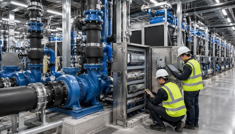
Mechanical engineering schedules for mission-critical facilities almost universally mandate N+1 or 2N redundancy for heat rejection infrastructure. A representative chilled water plant may specify four 1,200-ton centrifugal chillers, four primary chilled water pumps, and four condenser water pumps to support an N=3 design base. On process and instrumentation diagrams (P&IDs), each pump and chiller represents an isolated hydraulic and electrical entity, mechanically capable of carrying the design thermal load upon the physical failure of an adjacent unit. However, this mechanical segregation is frequently an illusion. In actual practice, these independent physical assets are bound together into an operational monolith by shared cyber-physical supervisory networks, common differential pressure sensors, aggregated control power rails, and centralized Programmable Logic Controller (PLC) routines.
Operational coupling occurs when supervisory automation systems prioritize global thermodynamic optimization over independent component survivability. High-efficiency data center designs incorporate complex plant optimization software targeting low Power Usage Effectiveness (PUE) and minimal mechanical lift. These supervisory engines dynamically alter chiller staging, modulate variable frequency drive (VFD) speed targets across parallel pump headers, and rebalance secondary cooling loops via motorized control valves. When the execution of basic fluid transport is subordinated to higher-level optimization code, the failure boundary ceases to be an individual pump or chiller. If an unhandled software exception, runtime memory leak, or communication timeout stalls the centralized supervisory controller, healthy mechanical assets with intact electrical feeds and pristine motor windings will sit idle simply because the centralized arbitration logic fails to issue a run command.
To establish true resilience, mission-critical facility designers must clearly distinguish between physical capacity redundancy and control domain autonomy. A failure domain encompasses the total envelope of infrastructure incapacitated by a single root-cause fault. When four mechanically independent pumps rely on a single supervisory controller to coordinate lead-lag assignments, that single controller defines the actual failure domain: N+1 mechanical capacity collapses into an N=0 operational outage. Establishing true operational independence requires tracing every non-mechanical umbilical, including secondary 24VDC control circuits, fieldbus communications, and process variable instrumentation, ensuring that no single failure mode cascades across independent physical assets.
Perform a comprehensive Cyber-Physical Failure Mode and Effects Analysis (FMEA) to identify non-mechanical coupling across all N+1 plant schedules.
Decouple basic operational sequencing from supervisory thermodynamic optimization routines to prevent software stalls from halting running machinery.
Establish physical, electrical, and logical boundaries such that the loss of any external communication signal defaults running equipment to a localized safe state.
Control Layer Vulnerabilities: BMS, Supervisory PLCs, Shared Networks, and Process Instrumentation
The control layer of a modern data center cooling plant typically features a hierarchy spanning field-level instrumentation, unit control panels (UCPs), plant-level supervisory PLCs, and centralized Building Management Systems (BMS). Communications across this hierarchy increasingly rely on networked fieldbuses utilizing protocols such as BACnet/IP, Modbus TCP, and PROFINET. Vulnerabilities multiply when these networks are implemented across flattened industrial Ethernet topologies. A broadcast storm generated by a faulty network interface card, a spanning tree protocol (STP) reconfiguration loop, or an unmanaged industrial Ethernet switch failure can instantaneously sever communications between plant PLCs and variable-speed drives. Deprived of cyclic state data, drive controllers programmed with default factory settings often trip offline on communication-loss faults, turning a minor network packet collision into an instantaneous loss of total fluid circulation.
Shared process instrumentation introduces severe common-mode physical vulnerabilities. In variable-primary chilled water architectures, pump speed is commonly modulated to maintain a target differential pressure (DP) across the hydraulically most remote cooling coil or index run. Cost-engineering frequently leads to the installation of a single DP transmitter array whose 4-20 mA analogue output is wired back to a central analog input module in the main supervisory PLC cabinet. If this single transmitter drifts, experiences an open circuit, or suffers water ingress, the supervisory control loop receives an invalid process variable. A sudden reading of 0 kPa causes the central PID algorithm to ramp all running pumps to 100% speed, triggering extreme overpressure, pipe hammer, and mechanical seal rupture; conversely, a high-pressure failure signal throttles all pumps to minimum speed, triggering immediate chiller evaporator freeze-stat trips across all running stages.
Control power topology represents another pervasive single point of failure within control panels. Industrial automation components rely on Class 2 24VDC switched-mode power supplies. In budget-constrained designs, a single 24VDC power supply unit (PSU) or an unmonitored non-redundant DC busbar distributes power across dozens of interposing relays, unit controller logic boards, and motorized valve actuators spanning multiple mechanical trains. A single dead-short within a modulating actuator solenoid on CRAH-1 pulls down the common 24VDC rail to zero volts, immediately crashing the microcontrollers inside CRAH-2, CRAH-3, and the standby unit. Without dedicated electronic circuit breakers capable of selective trip isolation, control power failure cascades instantaneously across the entire cooling zone.
Implement triplicated, 2-out-of-3 (2oo3) voting logic with independent physical impulse lines and galvanically isolated 4-20 mA loops for critical differential pressure control.
Deploy redundant Class 2 24VDC power supplies equipped with selective electronic circuit protection to guarantee that downstream short circuits remain isolated to an individual asset.
Isolate industrial fieldbus traffic using dedicated managed switches running deterministic media redundancy protocols (e.g., MRP or PRP/HSR) with strict broadcast storm rate limiting.
Liquid Cooling and CDU Proliferation: Compounding Failure Domain Risks
The rapid deployment of artificial intelligence (AI) and high-performance computing (HPC) clusters operating at rack power densities exceeding 40 kW to 100 kW has necessitated direct-to-chip (D2C) liquid cooling. At these thermal densities, the heat capacity of the air buffer is eliminated; thermal mass resides exclusively within the liquid volume of the secondary loop and the silicon cold plates. While a chilled water loop serving conventional Computer Room Air Handler (CRAH) units provides tens of minutes of thermal buffer during an operational upset, an AI server operating at maximum TDP will reach junction temperature limits (Tjmax) and initiate thermal throttling or hard emergency shutdown within 1.5 to 3 seconds of a complete loss of coolant flow.
Coolant Distribution Units (CDUs) are the mechanical interface between the Facility Water System (FWS) primary loop and the Technology Cooling System (TCS) secondary loop. To support high density, facilities deploy banks of CDUs in parallel, often designated as N+1 or N+2 at the row or room level. However, modern CDUs are highly complex, digitally integrated cyber-physical skids. Each unit contains integrated PLCs, dual variable-speed secondary pumps, primary modulating balancing valves, and comprehensive instrumentation monitoring pressure, flow rate, temperature, conductivity, and dissolved oxygen. When row-based CDUs report back to a centralized facility supervisor via Modbus RTU or BACnet/IP to orchestrate primary-side balancing valves, communication latencies or supervisory bus timeouts can freeze CDU secondary-to-primary heat rejection staging.
Supervisory coupling becomes particularly dangerous when CDU safety interlocks and leak detection architectures are centralized. Liquid cooling loops feature extensive leak detection ropes routed beneath quick-disconnect fittings, manifolds, and server chassis. If disparate leak detection loops are aggregated into a single supervisory safety module that issues an emergency isolation command over a software network, a single localized leak or sensor short-circuit in Rack 1 can trigger a supervisory cascade that isolates the TCS fluid supply to twenty adjacent, fully operational server cabinets. Designing for high-density AI demands that CDU safety logic and hydraulic control remain strictly localized, preventing localized physical faults from triggering global IT outages.
Enforce complete physical and control isolation for individual CDU secondary pumping and primary control valve loops, preventing supervisory bus dependencies.
Isolate leak detection interlocks to individual rack or manifold shut-off valves, barring supervisory controllers from broadcasting global secondary-loop shutdowns on localized leak events.
Audit dynamic thermal inertia across liquid cooling loops, ensuring local CDU pump failover and speed ramp-up execute within sub-second thresholds (<500 milliseconds).
Designing for Graceful Degradation: Autonomous Local Loops and Hardwired Fallbacks
Resilient data center engineering requires assuming the total loss of all supervisory control systems and designing deterministic mechanisms for graceful degradation. The core design principle is local control loop autonomy: every physical device must possess sufficient embedded intelligence to continue safe, baseline heat rejection without receiving data packets from an external network. Rather than relying on a centralized PLC to calculate PID outputs and transmit speed setpoints over a fieldbus, variable frequency drives must host their own internal PID algorithms. By wiring dedicated analog feedback signals directly into the drive's local terminal strip, the pump or fan modulates its own speed based on direct physical conditions, completely immune to the health of the wider automation network.
Graceful degradation requires the implementation of hardwired analog and digital fallbacks that bypass microprocessors entirely upon supervisory failure. Critical control valves—such as primary chiller isolation valves, CDU bypass valves, and CRAH 2-way water valves—must be specified with mechanical spring-return actuators or fail-in-place electronic controls. In the event of a total control power outage or signal line breakage (e.g., loss of 0-10V or 4-20 mA control voltage), these actuators must mechanically bias to a predetermined safe position: typically 100% open to cooling and 0% open to bypass. This guarantees that fluid circulation continues passively via hydraulic head, preventing rapid thermal runaway across mission-critical compute surfaces.
To govern the transition between optimized supervisory control and autonomous local operation, field devices must employ robust communication watchdog timers. A supervisory controller must continuously transmit a dynamic heartbeat signal to every connected device controller. If a drive, CRAH unit controller, or CDU PLC fails to receive a valid heartbeat within an engineered window (typically 5 to 15 seconds), it must immediately disengage supervisory authority, log a network degradation event, and transition into an autonomous fallback mode. Depending on the process engineering requirements, this mode may entail locking the output to the last known valid setpoint, defaulting to a conservative fixed-speed baseline (such as 85% nominal RPM), or switching to an internal, localized PID loop running off local sensors.
Configure bidirectional communication watchdog timers on all VFDs and unit controllers with deterministic fallback actions (fail-to-last-speed or fail-to-preset-speed).
Engineer hardwired, analog overrides and spring-return valve actuator mechanics that force open critical heat rejection pathways upon total loss of control signal.
Program autonomous PID control loops locally inside individual equipment controllers using hardwired analog instrumentation, eliminating supervisory bus dependencies for basic process control.
Advanced Commissioning Protocols: Testing the Control Failure Domain, Not Just Assets
Traditional Level 4 and Level 5 Integrated Systems Testing (IST) protocols frequently mask critical control vulnerabilities by testing only the physical operational envelope. In a conventional commissioning sequence, a commissioning agent manually trips the primary breaker of an operating pump to observe whether the standby pump starts within the specified changeover window. While this test validates that the standby motor spins and the mechanical check valve seats properly, it only exercises standard, non-faulted automation sequences running under healthy supervisory control. It completely fails to reveal what occurs when the control infrastructure that commands that changeover sequence is the component that actually fails.
Advanced failure-domain commissioning mandates disruptive, destructive testing targeted specifically at the control and automation layer under full thermal heat load. Commissioning agents must physically sever industrial Ethernet connections between the central PLC rack and the motor control centers (MCCs) while the plant operates at maximum capacity. This test proves whether the variable frequency drives gracefully transition to their autonomous fallback speeds or whether they trip offline on communication-timeout faults. Similarly, testing must involve power-cycling the main BMS supervisory server, disconnecting the 24VDC power supply to the supervisory I/O modules, and injecting simulated network broadcast storms into fieldbus switches to evaluate system resilience under acute cyber-physical stress.
Furthermore, process instrumentation resilience must be validated via hardwired fault injection at the sensor terminal blocks. Rather than testing sensor calibration in isolation, commissioning agents must simulate open-circuit (0 mA), short-circuit (>21 mA), and slow sensor drift conditions on primary chilled water differential pressure sensors, supply temperature wells, and CDU flow meters. These tests verify that the PLC and local drive logic identify signal unreasonableness (out-of-range sensor diagnostic alarms), reject corrupted data, prevent PID windup, and transfer process authority to secondary redundant sensors or predetermined fallback profiles without causing hydraulic oscillation or equipment trips.
Execute live supervisory network severance and broadcast storm injection tests under full thermal load to verify continuous, uninterrupted mechanical operation.
Perform destructive control power dropout tests by de-energizing individual 24VDC power supplies and shared busbars to validate downstream circuit selectivity and autonomous operation.
Conduct signal fault injection at instrument terminal blocks (open circuit, short circuit, and signal drift) to confirm sensor plausibility logic and automatic fallback execution.
Engineering Checklist and Resilience Governance for High-Density AI Facilities
Sustaining operational resilience across the multi-decade lifecycle of an AI-era data center requires transitioning from ad-hoc control management to formalized cyber-physical automation governance. In high-density facilities, control software, firmware versions, and network configurations must be subjected to the same rigorous engineering discipline as medium-voltage switchgear and primary piping headers. A major driver of operational drift in live facilities is unauthorized field modifications: technicians tweaking a PID gain, bypassing a watchdog timer to silence a nuisance alarm, or daisy-chaining an unmanaged network switch to bridge two physically separate cooling rows. Over time, these well-intentioned field interventions erode designed-in failure domain boundaries.
A rigorous governance framework requires maintaining an active, audited Failure Domain Matrix for the entire cooling plant. This engineering artifact maps every single physical asset (chiller, pump, cooling tower fan, CDU, isolation valve) against its associated supervisory PLC, network switch port, control power circuit breaker, and process instrumentation loop. No facility modification, mechanical expansion, or control code update should be permitted without an engineering review against this matrix to confirm that no new shared dependencies have been inadvertently introduced. Furthermore, high-density AI data centers must institutionalize mandatory annual destructive control testing during planned maintenance windows, ensuring that degraded-mode autonomous fallbacks remain fully functional as operational software evolves.
Establish and maintain a comprehensive Failure Domain Matrix that maps every physical cooling asset to its specific cyber-physical, electrical, and sensor dependencies.
Enforce strict change management protocols prohibiting unversioned code modifications, manual supervisory overrides, or cross-train network bridging in live production environments.
Mandate annual destructive integrated systems re-testing during planned maintenance windows to empirically prove the operational survivability of autonomous degraded modes.
Engineering Procurement & Technical Desk
For technical datasheets, custom power topology design, or volume export quotations, reach out to HEFENGQI engineers.